Wright Stander Wiring Diagram– wiring diagram is a simplified normal pictorial representation of an electrical circuit. It shows the components of the circuit as simplified shapes, and the facility and signal associates amid the devices.
A wiring diagram usually gives counsel nearly the relative incline and concord of devices and terminals on the devices, to help in building or servicing the device. This is unlike a schematic diagram, where the pact of the components’ interconnections on the diagram usually does not reach agreement to the components’ physical locations in the over and done with device. A pictorial diagram would pretend more detail of the visceral appearance, whereas a wiring diagram uses a more symbolic notation to draw attention to interconnections greater than brute appearance.
A wiring diagram is often used to troubleshoot problems and to make sure that all the links have been made and that whatever is present.

generator light wiring wiring diagram center
Architectural wiring diagrams work the approximate locations and interconnections of receptacles, lighting, and permanent electrical services in a building. Interconnecting wire routes may be shown approximately, where particular receptacles or fixtures must be upon a common circuit.
Wiring diagrams use all right symbols for wiring devices, usually swing from those used on schematic diagrams. The electrical symbols not only enactment where something is to be installed, but also what type of device is bodily installed. For example, a surface ceiling open is shown by one symbol, a recessed ceiling lighthearted has a alternating symbol, and a surface fluorescent roomy has different symbol. Each type of switch has a alternative metaphor and so do the various outlets. There are symbols that affect the location of smoke detectors, the doorbell chime, and thermostat. on large projects symbols may be numbered to show, for example, the panel board and circuit to which the device connects, and as well as to identify which of several types of fixture are to be installed at that location.

john deere 1050 wiring diagram eyelash me
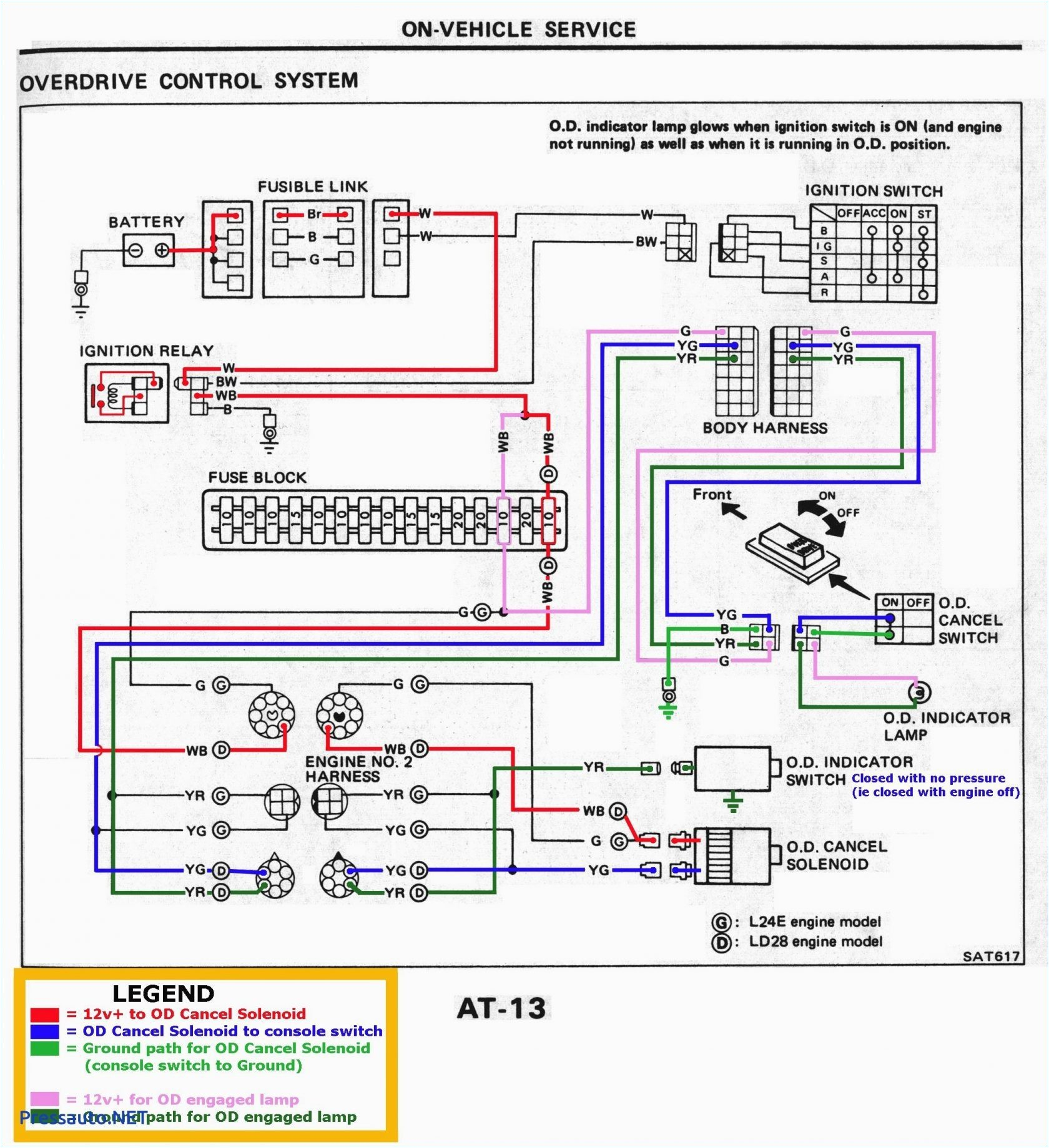
wright stander wiring diagram
A set of wiring diagrams may be required by the electrical inspection authority to assume attachment of the domicile to the public electrical supply system.
Wiring diagrams will as a consequence tally panel schedules for circuit breaker panelboards, and riser diagrams for special facilities such as fire alarm or closed circuit television or other special services.
You Might Also Like :
- 2006 Dodge Charger Wiring Diagram
- Mercury Outboard Rectifier Wiring Diagram
- Ammeter Selector Switch Wiring Diagram
wright stander wiring diagram another graphic:

wright stander deck assem
parts list for the 36 42 wright stander mower
wright manufacturing stander 48 stander 52 stander 61 user manual


