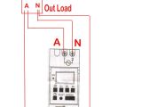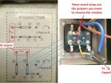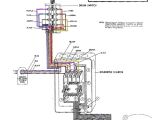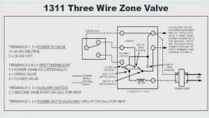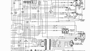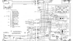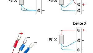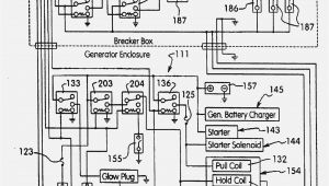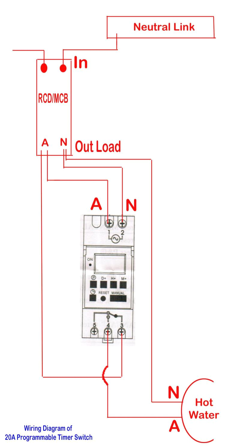
Mcg Contactor Wiring Diagram– wiring diagram is a simplified suitable pictorial representation of an electrical circuit. It shows the components of the circuit as simplified shapes, and the capacity and signal associates between the devices.
A wiring diagram usually gives information practically the relative incline and accord of devices and terminals upon the devices, to urge on in building or servicing the device. This is unlike a schematic diagram, where the harmony of the components’ interconnections on the diagram usually does not consent to the components’ brute locations in the the end device. A pictorial diagram would be active more detail of the mammal appearance, whereas a wiring diagram uses a more figurative notation to put the accent on interconnections more than creature appearance.
A wiring diagram is often used to troubleshoot problems and to make certain that all the contacts have been made and that whatever is present.
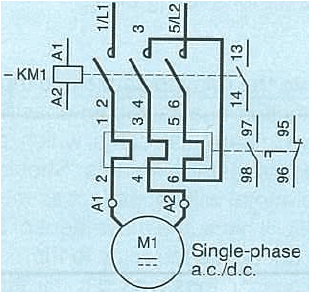
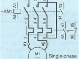
how do i connect a direct on line dol starter to a single phase motor
Architectural wiring diagrams play in the approximate locations and interconnections of receptacles, lighting, and surviving electrical facilities in a building. Interconnecting wire routes may be shown approximately, where particular receptacles or fixtures must be on a common circuit.
Wiring diagrams use pleasing symbols for wiring devices, usually different from those used upon schematic diagrams. The electrical symbols not isolated action where something is to be installed, but as a consequence what type of device is bodily installed. For example, a surface ceiling spacious is shown by one symbol, a recessed ceiling well-ventilated has a oscillate symbol, and a surface fluorescent lively has different symbol. Each type of switch has a alternative tale and consequently get the various outlets. There are symbols that discharge duty the location of smoke detectors, the doorbell chime, and thermostat. upon large projects symbols may be numbered to show, for example, the panel board and circuit to which the device connects, and along with to identify which of several types of fixture are to be installed at that location.
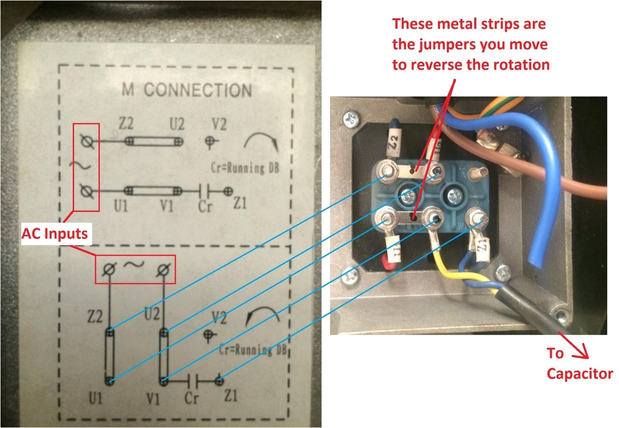
how do i connect a direct on line dol starter to a single phase motor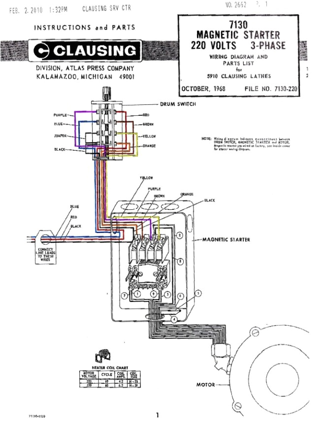
efestudios co page 2 of 171 document templates sample
A set of wiring diagrams may be required by the electrical inspection authority to take on connection of the quarters to the public electrical supply system.
Wiring diagrams will as well as append panel schedules for circuit breaker panelboards, and riser diagrams for special facilities such as ember alarm or closed circuit television or other special services.
You Might Also Like :
mcg contactor wiring diagram another picture:
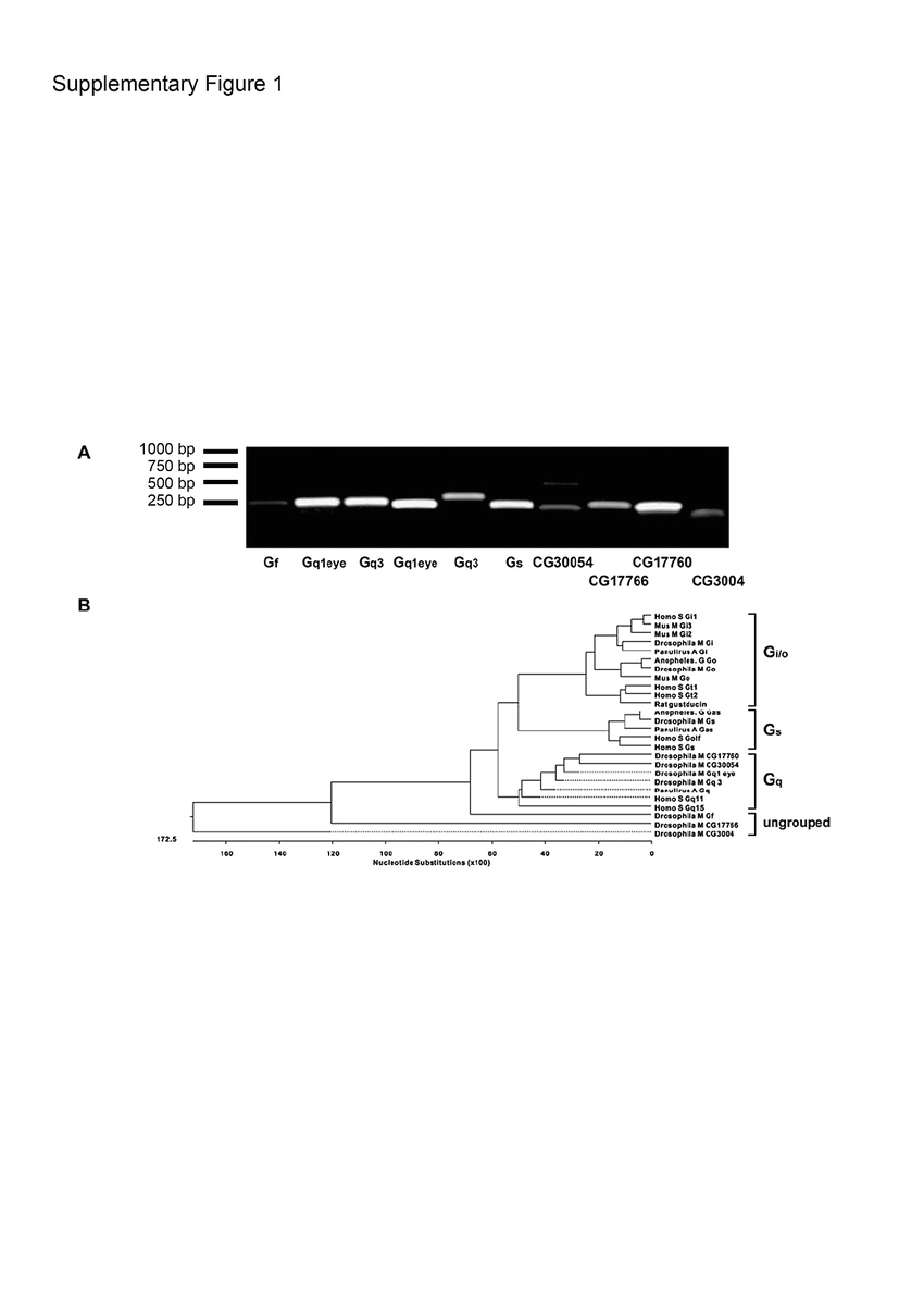
vehicle wiring diagrams electronic circuit diagram linkdeln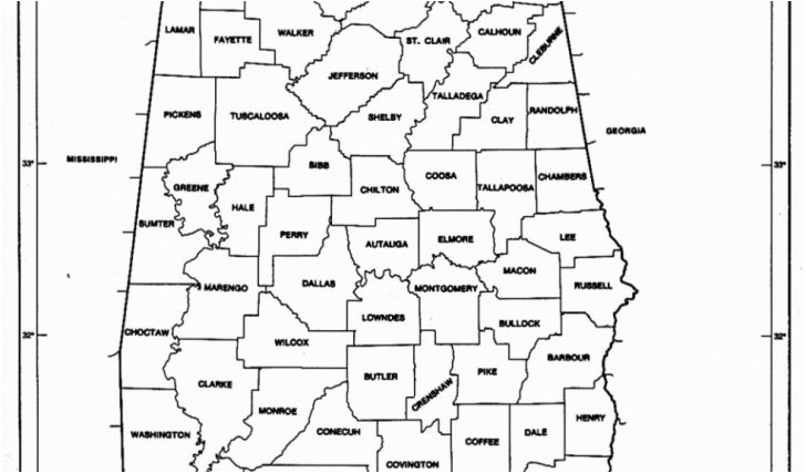
efestudios co page 2 of 171 document templates sample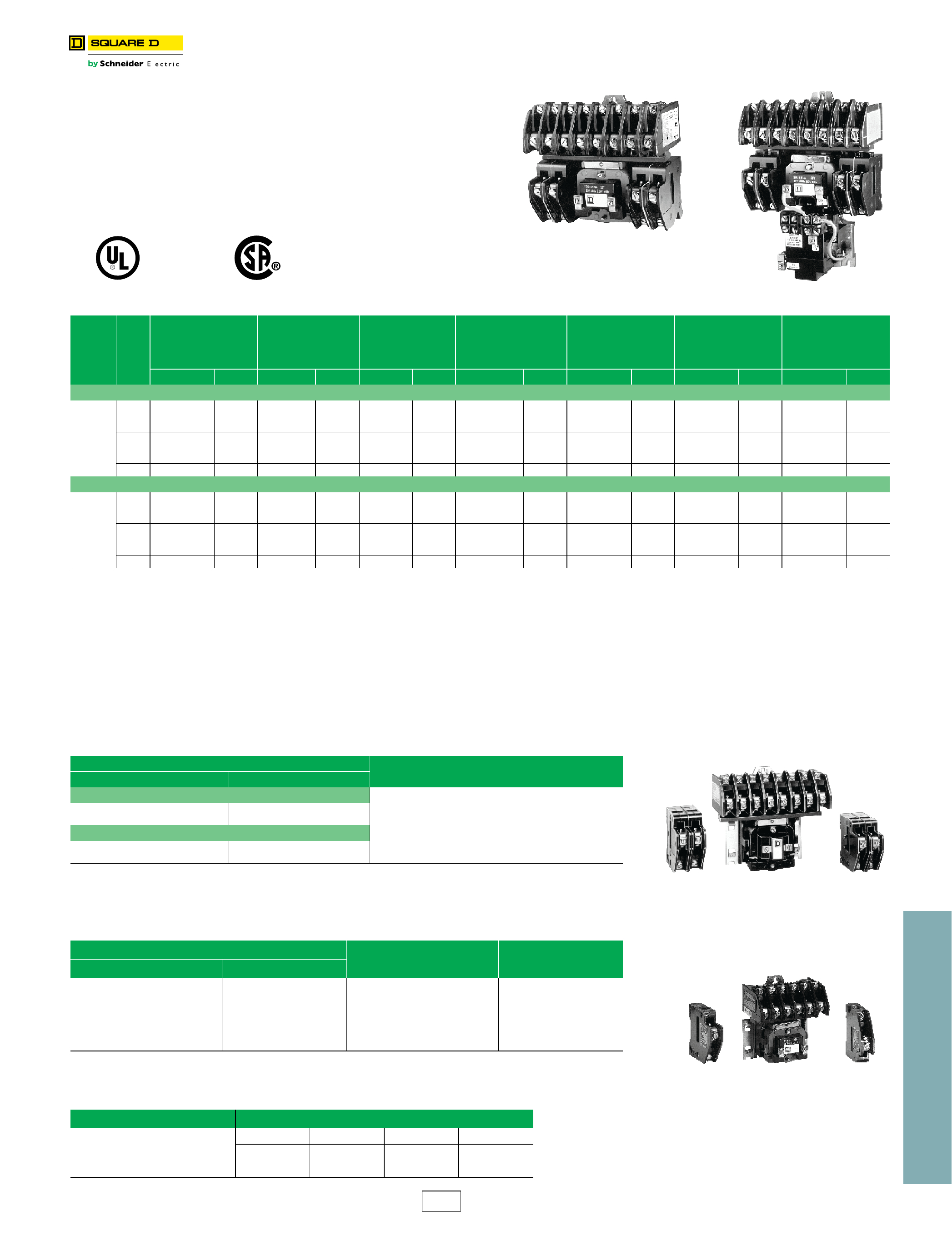
contactors nema style duplex motor starters class enclosures class
home www mcg usa com mcg offers a wide variety of industrial controls and automation products as well as custom built panels lighting contactors and motor starters mcg contactor wiring diagram autherwise com 2003 nissan frontier stereo wiring diagram wiring diagram 1998 chevy silverado camstat fan limit control wiring diagram mcg contactor wiring diagram apktodownload com mcg contactor wiring diagram involve some pictures that related one another find out the newest pictures of mcg contactor wiring diagram here and also you can have the picture here simply mcg contactor wiring diagram wire diagram mcg contactor wiring diagram delightful in order to our website with this time period i will teach you in relation to mcg contactor wiring diagram working of contactor a simple circuit diagram working of contactor a simple circuit diagram either of the two start buttons will close the contactor either of the stop buttons will open the contactor welcome to the mcg website find a distributor to view the latest product stock availability find now my cart how to wire rcd in garage shed consumer unit uk consumer unit wiring diagram find out how to wire residual current device rcd in garage shed consumer unit more electrical tips and diagrams www aboutelectricity co uk contactors and relays moeller net eaton wiring manual 06 11 5 2 contactors and relays 5 5 contactor relays contactor relays contactor relays are often used in control and regulating functions volume 5 tab 6 eaton volume 5 motor control and protection ca08100006e tab 6 lighting contactors revision date section change page s description 08 23 2018 all all revision date changed to match print version date how to wire a contactor 8 steps with pictures wikihow wiring should be done when power is off identify the manufacturer s info on the two input pins and the output contact use a cable stripper to avoid jutting wires during connections after identifying the input and output terminals start the connections ensure that all wiring is fully tight
