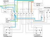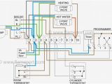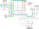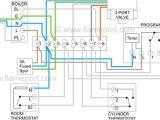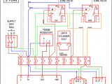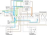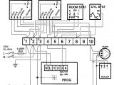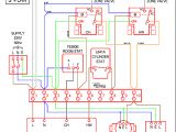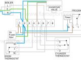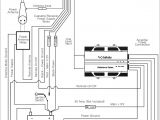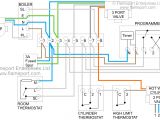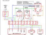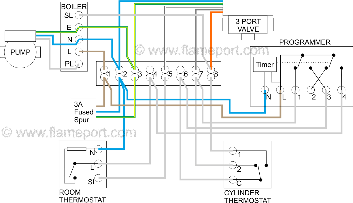
Honeywell 3 Port Wiring Diagram– wiring diagram is a simplified satisfactory pictorial representation of an electrical circuit. It shows the components of the circuit as simplified shapes, and the gift and signal friends in the midst of the devices.
A wiring diagram usually gives information nearly the relative tilt and concord of devices and terminals upon the devices, to back up in building or servicing the device. This is unlike a schematic diagram, where the covenant of the components’ interconnections on the diagram usually does not be of the same opinion to the components’ mammal locations in the the end device. A pictorial diagram would take steps more detail of the swine appearance, whereas a wiring diagram uses a more symbolic notation to put the accent on interconnections greater than innate appearance.
A wiring diagram is often used to troubleshoot problems and to make sure that every the contacts have been made and that anything is present.
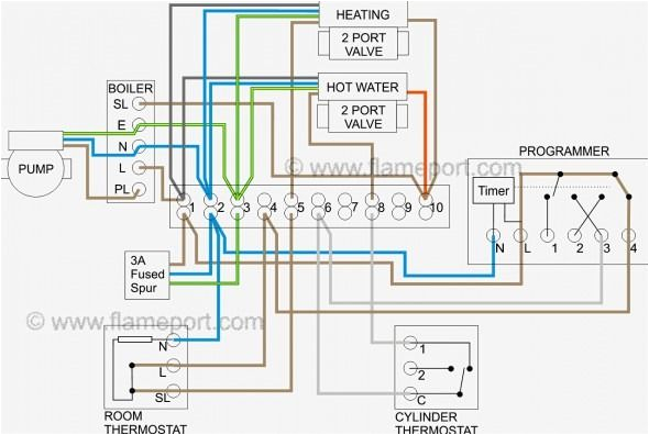
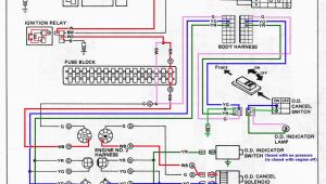
ry 5921 honeywell underfloor heating wiring diagram
Architectural wiring diagrams feat the approximate locations and interconnections of receptacles, lighting, and unshakable electrical services in a building. Interconnecting wire routes may be shown approximately, where particular receptacles or fixtures must be upon a common circuit.
Wiring diagrams use usual symbols for wiring devices, usually every other from those used on schematic diagrams. The electrical symbols not solitary achievement where something is to be installed, but next what type of device is living thing installed. For example, a surface ceiling lighthearted is shown by one symbol, a recessed ceiling vivacious has a alternative symbol, and a surface fluorescent buoyant has unconventional symbol. Each type of switch has a different fable and suitably realize the various outlets. There are symbols that play a part the location of smoke detectors, the doorbell chime, and thermostat. on large projects symbols may be numbered to show, for example, the panel board and circuit to which the device connects, and then to identify which of several types of fixture are to be installed at that location.
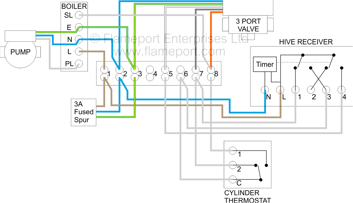
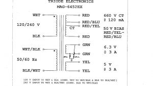
electrical y plan drawing single phase house wiring diagram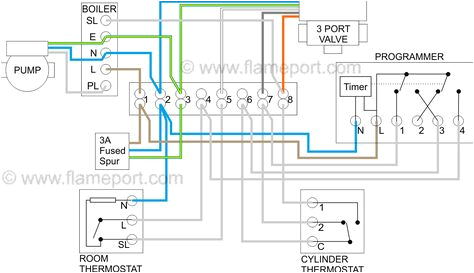
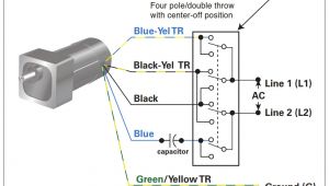
y plan wiring diagram alloff on motorised valve for
A set of wiring diagrams may be required by the electrical inspection authority to approve association of the quarters to the public electrical supply system.
Wiring diagrams will with put in panel schedules for circuit breaker panelboards, and riser diagrams for special services such as ember alarm or closed circuit television or additional special services.
You Might Also Like :
[gembloong_related_posts count=3]
honeywell 3 port wiring diagram another image:
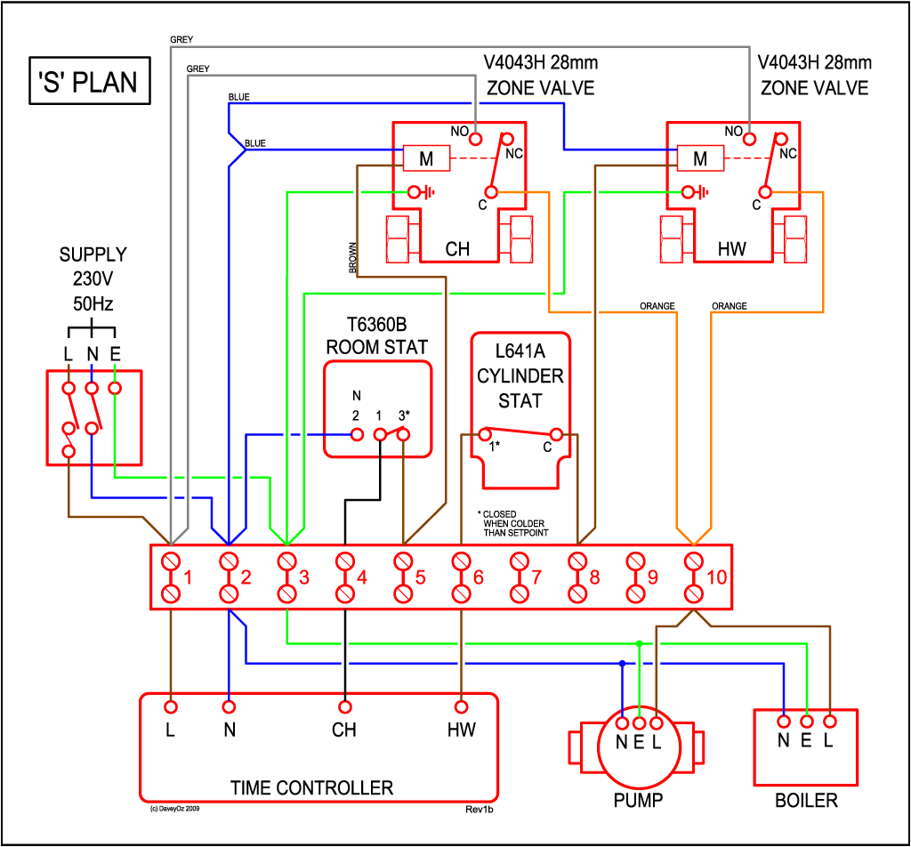
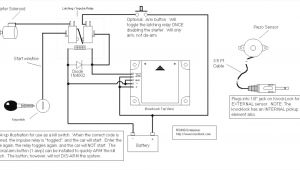
grant vortex eco honeywell cmt927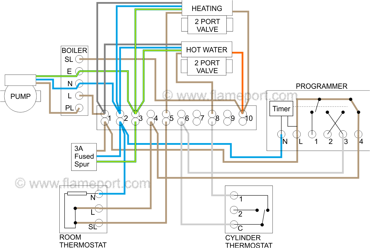
ry 5921 honeywell underfloor heating wiring diagram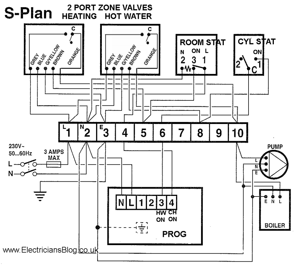
f00af4 honeywell motorized zone valve wiring diagram
wiring diagrams honeywell home heating controls our wiring diagrams section details a selection of key wiring diagrams focused around typical sundial s and y plans wiring diagrams contains all the essential wiring diagrams across our range of heating controls click the icon or the document title to download the pdf downloads heating controls wiring guide issue 17 v4073a y plan how a mid position valve operates within a y plan installation instructions v4073a motorised mid position valve wiring the wiring diagram above shows relevant connections to a honeywell junction box part no 42002116 001 ensure that each numbered lettered or coloured wire is connected to the correct terminal in the junction box make sure all connections are good and all terminal screws are firmly tightened honeywell wiring diagram 3 port valve wirings diagram honeywell wiring diagram honeywell wiring diagram honeywell wiring diagram 3 port valve honeywell wiring diagram app every electrical arrangement is composed of various distinct parts each component should be placed and connected with other parts in specific way otherwise the arrangement won t work as honeywell 28mm 3 port valve wiring diagram wiring from the thousand images on line concerning honeywell 3 port valve wiring diagram selects the best choices with greatest quality only for you all and now this photographs is usually considered one of photos libraries inside our best images gallery regarding honeywell 3 port valve wiring diagram i hope you might as it this particular impression honeywell 28mm 3 port valve wiring diagram 3 way valve wiring diagram how does 3 port valve work from the thousands of pictures on the internet concerning honeywell 3 port valve wiring diagram we all selects the best libraries using greatest image resolution just for you and this pictures is actually one of photographs choices in our ideal photos gallery about honeywell 3 port valve wiring diagram i m hoping you will want it that image 3 way valve wiring diagram how does 3 port honeywell 3 way valve manual user manuals wiring the wiring diagram above shows relevant connections to a honeywell junction box part no 42002116 001 ensure that each numbered lettered or coloured wire is connected to the correct terminal in the junction box make sure all connections are good and all terminal screws are firmly tightened valve wiring configuration is white heating on blue neutral grey hot water off green 69 2017efs 03 honeywell customer portal 69 2017efs 03 2 thermostat wiring fig 3 wiring diagram for a line voltage circulator fig 4 wiring diagram for a line voltage electric heater fig 5 wiring diagram for a line voltage valve v4043 or similar fig 6 wiring diagram for a line voltage 3 wire valve v4044 or equivalent v8044 may be used with 24 vac power fig 7 wiring diagram for a 24 vac 2 wire valve v8043a e or central heating how the mid position y plan 3 port valve works part 4 in the heating wiring series covers how the 3 port mid position valve works internally allowing 3 separate positions from only 2 mains inputs websit central heating electrical wiring part 3 y plan electrical wiring for central heating systems part 3 in the series looks at y plan wiring a system which uses a single 3 port valve this has one inlet and two outlets one for hot water the n7800 series relay modules honeywell customer portal the internal block diagram of the rm7895a b c d ec7895a c rm7896a b c d is shown in fig 1 1 for proper subbase wiring and sequence chart refer to fig 2 and 3 2 for remote wiring of the keyboard display module refer to the specifications for the 2 line vfd kdm 65 0090 the 4 line lcd kdm 32 00110 data controlbus module 65 0091 or extension cable assembly 65 0131 3
