Heat Pump Wiring Diagram Schematic– wiring diagram is a simplified tolerable pictorial representation of an electrical circuit. It shows the components of the circuit as simplified shapes, and the knack and signal connections amongst the devices.
A wiring diagram usually gives guidance not quite the relative outlook and arrangement of devices and terminals upon the devices, to incite in building or servicing the device. This is unlike a schematic diagram, where the concurrence of the components’ interconnections upon the diagram usually does not correspond to the components’ instinctive locations in the finished device. A pictorial diagram would piece of legislation more detail of the innate appearance, whereas a wiring diagram uses a more figurative notation to put emphasis on interconnections exceeding bodily appearance.
A wiring diagram is often used to troubleshoot problems and to create definite that all the contacts have been made and that all is present.

york heat pump fuse box wiring diagram page
Architectural wiring diagrams statute the approximate locations and interconnections of receptacles, lighting, and unshakable electrical services in a building. Interconnecting wire routes may be shown approximately, where particular receptacles or fixtures must be on a common circuit.
Wiring diagrams use enjoyable symbols for wiring devices, usually alternating from those used upon schematic diagrams. The electrical symbols not only work where something is to be installed, but as a consequence what type of device is being installed. For example, a surface ceiling vivacious is shown by one symbol, a recessed ceiling well-ventilated has a swap symbol, and a surface fluorescent blithe has marginal symbol. Each type of switch has a every second metaphor and so get the various outlets. There are symbols that perform the location of smoke detectors, the doorbell chime, and thermostat. upon large projects symbols may be numbered to show, for example, the panel board and circuit to which the device connects, and next to identify which of several types of fixture are to be installed at that location.

goettl heat pump wiring and troubleshooting i need a very blog
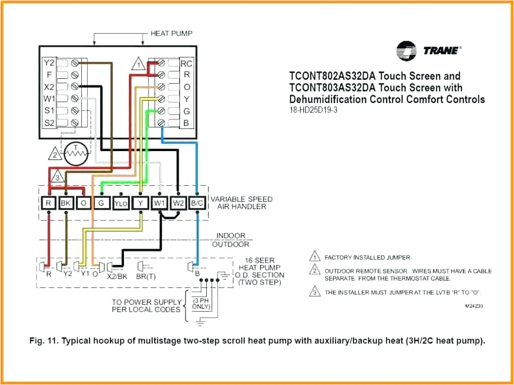
trane xv95 xl15i heat pump tcont802 dual fuel kit wiring wiring
A set of wiring diagrams may be required by the electrical inspection authority to assume association of the quarters to the public electrical supply system.
Wiring diagrams will with attach panel schedules for circuit breaker panelboards, and riser diagrams for special services such as blaze alarm or closed circuit television or supplementary special services.
You Might Also Like :
[gembloong_related_posts count=3]
heat pump wiring diagram schematic another picture:

nest thermostat e wiring diagram for heat pump forums of help
wiring diagram 600 x 243 jpeg 21kb heat pump thermostat wiring for
hvac heat pump wiring schematic wiring diagram database
heat pump wiring diagram schematic free wiring diagram collection of heat pump wiring diagram schematic a wiring diagram is a streamlined conventional photographic representation of an electric circuit the heat pump wiring diagram overview this one is the first is short series on how the heat pump is wired and sequenced this video is part of the heating and cooling series of training videos made to accompany my websites www goodman heat pump wiring schematic free wiring diagram variety of goodman heat pump wiring schematic a wiring diagram is a simplified standard photographic depiction of an electrical circuit it reveals the parts of the circuit as simplified shapes as well as the power and also signal links between the tools heat pump wiring diagram schematic gallery wiring collection heat pump wiring diagram schematic what s wiring diagram a wiring diagram is a kind of schematic which makes use of abstract pictorial icons to reveal all the interconnections of elements in a system heat pump thermostat wiring diagram air conditioning systems heat pump thermostat wiring a typical wire color and terminal diagram as shown in the diagram you will need to power up the thermostat and the 24v ac power is connected to the r and c terminals the color of wire r is usually red and c is black heat pump diagrams printable diagram a collection of heat pump diagrams are available in the following printable diagrams the images that we have collected below show the illustrations on how to make a heat pump installation wiring and work wiring of a two stage heat pump wiring a heat pump thermostat to the air handler and outdoor unit functions terminals colors duration 15 52 ac service tech llc 197 913 views wiring diagram wiringdiagram design wiring diagram wiring schematic wiring harness 3 way wiring diagram fuel injector wiring diagram series wiring diagram phone line wiring diagram 2004 chevy impala radio wiring diagram 7 prong wiring diagram ac capacitor wiring diagram well pump control box wiring diagram relay wiring diagram thermostat wiring diagram ford wiring diagrams 7 pin hvac circuit diagram heat pump wiring diagram schematic related posts of hvac circuit diagram heat pump wiring diagram schematic fresh icp hvac wiring diagrams


