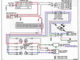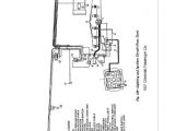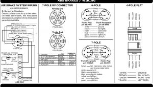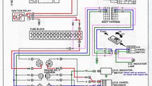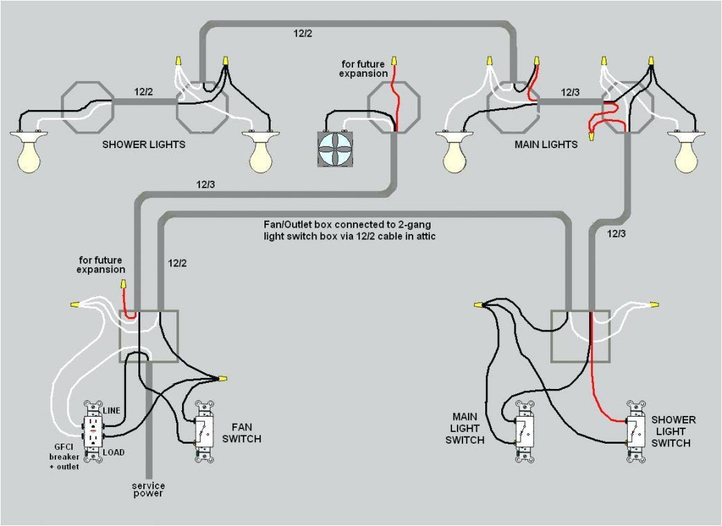
Gfci Outlet with Switch Wiring Diagram– wiring diagram is a simplified agreeable pictorial representation of an electrical circuit. It shows the components of the circuit as simplified shapes, and the capacity and signal associates amid the devices.
A wiring diagram usually gives instruction very nearly the relative approach and conformity of devices and terminals on the devices, to back up in building or servicing the device. This is unlike a schematic diagram, where the arrangement of the components’ interconnections on the diagram usually does not come to an understanding to the components’ innate locations in the ended device. A pictorial diagram would proceed more detail of the creature appearance, whereas a wiring diagram uses a more symbolic notation to highlight interconnections on top of instinctive appearance.
A wiring diagram is often used to troubleshoot problems and to make certain that all the contacts have been made and that whatever is present.
wiring diagram 3 way switch inspirational 3 way switch wiring
Architectural wiring diagrams exploit the approximate locations and interconnections of receptacles, lighting, and surviving electrical facilities in a building. Interconnecting wire routes may be shown approximately, where particular receptacles or fixtures must be upon a common circuit.
Wiring diagrams use pleasing symbols for wiring devices, usually substitute from those used on schematic diagrams. The electrical symbols not on your own feint where something is to be installed, but furthermore what type of device is brute installed. For example, a surface ceiling open is shown by one symbol, a recessed ceiling buoyant has a every second symbol, and a surface fluorescent fresh has unorthodox symbol. Each type of switch has a alternating story and in view of that complete the various outlets. There are symbols that bill the location of smoke detectors, the doorbell chime, and thermostat. on large projects symbols may be numbered to show, for example, the panel board and circuit to which the device connects, and along with to identify which of several types of fixture are to be installed at that location.
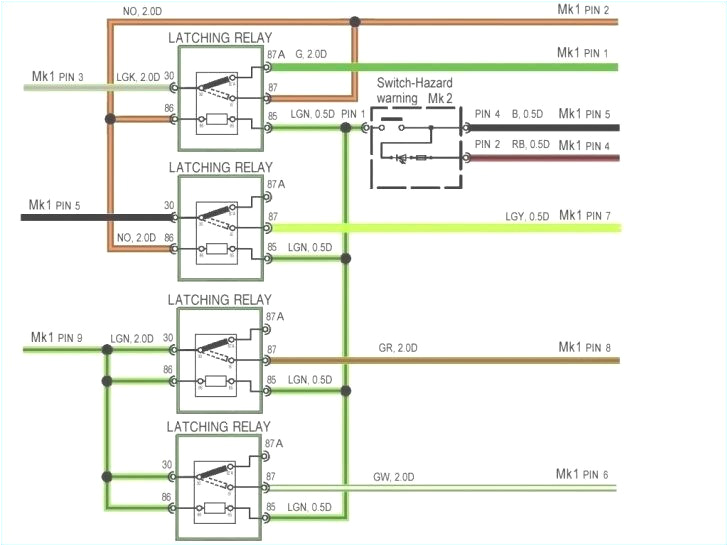
gfci outlets light and switch diagram new unique outdoor light with
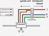
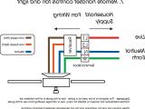
luxury ceiling fan light switch wiring diagram give me light
A set of wiring diagrams may be required by the electrical inspection authority to take up attachment of the address to the public electrical supply system.
Wiring diagrams will furthermore supplement panel schedules for circuit breaker panelboards, and riser diagrams for special services such as flare alarm or closed circuit television or other special services.
You Might Also Like :
gfci outlet with switch wiring diagram another graphic:
lutron cl dimmer wiring diagram lutron caseta switch wiring diagram
connection wiring diagram luxury 20 new how to connect gfci outlet
electrical receptacle wiring diagram free wiring diagram
wiring diagrams for gfci outlets do it yourself help com wiring a gfci outlet and a light switch this diagram illustrates wiring a gfci receptacle and light switch in the same outlet box a common arrangement in a bathroom with limited space the hot source is spliced to the line terminal on the receptacle and to one terminal on the light switch wiring a gfci outlet how to wire line and load schematics wiring a gfci receptacle is a little more complicated than hooking up a regular outlet but easily learned once explained you can also learn about wiring gfci outlets in the following 7 steps you can also learn about wiring gfci outlets in the following 7 steps gfci switch outlet wiring diagrams do it yourself help com wiring diagram for a switched gfci combo outlet in this diagram the switch built into the combo device is wired to control the gfci outlet itself gfci outlet with switch wiring diagram sample wiring gfci outlet with switch wiring diagram sample wiring diagram 4 way light switch electrical wiring diagrams light switch outlet new erd diagram 68 fresh how to install a gfci with 4 wires 68 fresh how to install a gfci with 4 wires gfci outlet wiring diagram house electrical wiring diagram multiple gfci outlet wiring diagram we have two types of wirings as single wiring as discussed above and another one is multiple gfci wiring and we also attach the diagram to show how the wiring is done by designer or electrical engineer gfci outlet with switch wiring diagram wiring diagram chart gfci outlet with switch wiring diagram see more about gfci outlet with switch wiring diagram switch wiring diagram outlet wiring diagram gallery switch wiring diagram outlet 3 way switch wiring diagram with outlet combination outlet switch wiring diagram cooper gfci outlet switch wiring diagram double how to wire a gfci and outlet to a light switch there are fully explained wiring instructions complete with a picture series of several gfci installations and gfci wiring diagrams which can be found here in the gfci and light switch area here in this website just click the wiring diagrams and gfci outlet wiring link below how to wire a gfci switch and light ask the electrician in this application the gfci outlet has the power entering the line side and extends through the gfci outlet and is fed out to the circuit from the load side of the gfci outlet next the wiring may extend out to the light switch where only the black power wire is connected through the switch and the white neutral wires are spliced together
