Flasher Wiring Diagram– wiring diagram is a simplified all right pictorial representation of an electrical circuit. It shows the components of the circuit as simplified shapes, and the capability and signal links in the midst of the devices.
A wiring diagram usually gives guidance about the relative viewpoint and promise of devices and terminals upon the devices, to encourage in building or servicing the device. This is unlike a schematic diagram, where the contract of the components’ interconnections on the diagram usually does not reach agreement to the components’ physical locations in the ended device. A pictorial diagram would do its stuff more detail of the subconscious appearance, whereas a wiring diagram uses a more figurative notation to emphasize interconnections over being appearance.
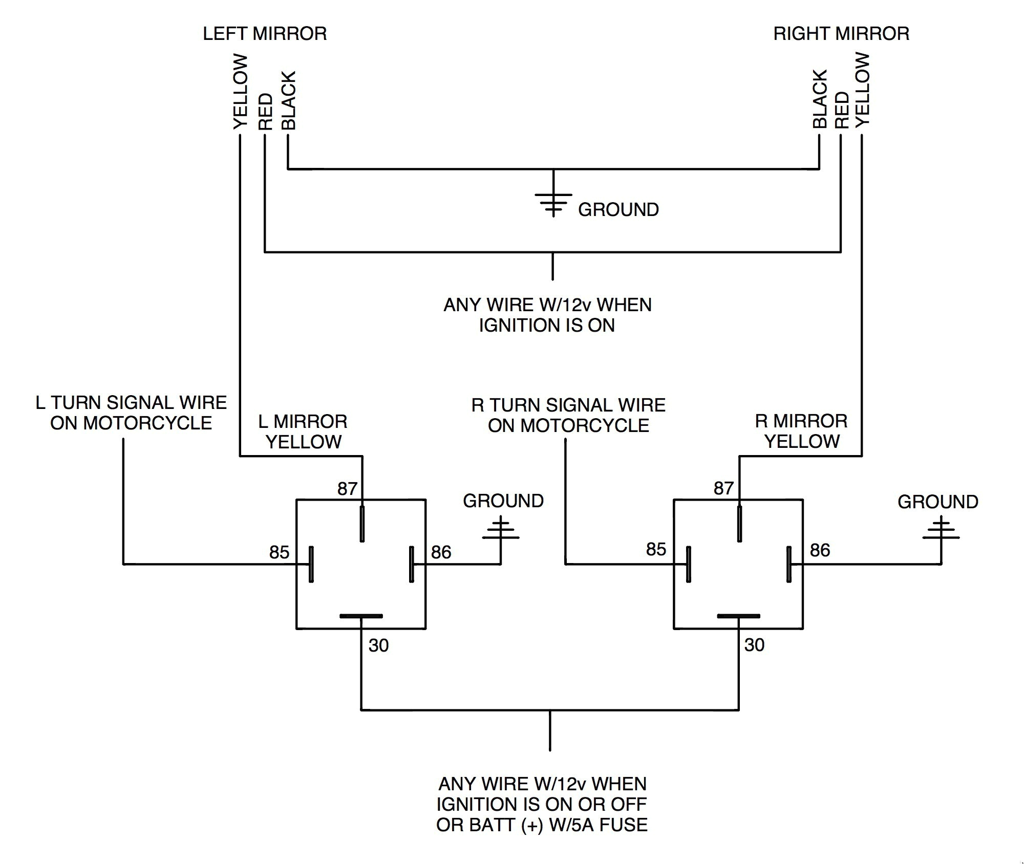
A wiring diagram is often used to troubleshoot problems and to create definite that all the associates have been made and that whatever is present.

turn signal flasher wiring diagram wire diagram
Architectural wiring diagrams operate the approximate locations and interconnections of receptacles, lighting, and permanent electrical facilities in a building. Interconnecting wire routes may be shown approximately, where particular receptacles or fixtures must be on a common circuit.
Wiring diagrams use adequate symbols for wiring devices, usually alternative from those used upon schematic diagrams. The electrical symbols not lonely ham it up where something is to be installed, but after that what type of device is bodily installed. For example, a surface ceiling lighthearted is shown by one symbol, a recessed ceiling well-ventilated has a oscillate symbol, and a surface fluorescent lighthearted has other symbol. Each type of switch has a vary symbol and so reach the various outlets. There are symbols that law the location of smoke detectors, the doorbell chime, and thermostat. on large projects symbols may be numbered to show, for example, the panel board and circuit to which the device connects, and also to identify which of several types of fixture are to be installed at that location.

signal light flasher wiring diagram elegant turn signal wiring
signal light flasher wiring diagram best of signal light flasher
A set of wiring diagrams may be required by the electrical inspection authority to take up relationship of the quarters to the public electrical supply system.
Wiring diagrams will in addition to add together panel schedules for circuit breaker panelboards, and riser diagrams for special facilities such as fire alarm or closed circuit television or further special services.
You Might Also Like :
flasher wiring diagram another graphic:

signal light flasher wiring diagram elegant turn signal wiring
signal light flasher wiring diagram best of wiring diagrams for turn
2 pin flasher relay wiring diagram unique electronic flasher relay


