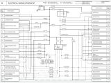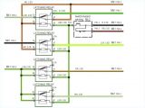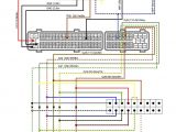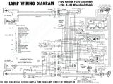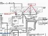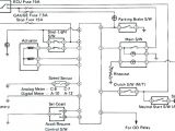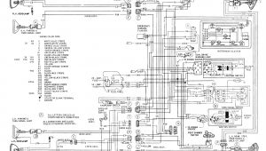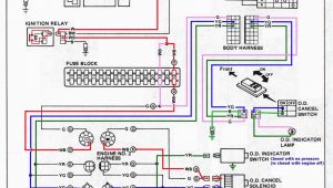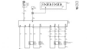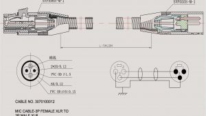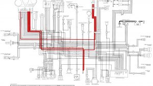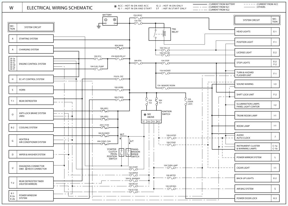
Ecu Wiring Diagram– wiring diagram is a simplified pleasing pictorial representation of an electrical circuit. It shows the components of the circuit as simplified shapes, and the capacity and signal links in the midst of the devices.
A wiring diagram usually gives assistance just about the relative perspective and understanding of devices and terminals on the devices, to back up in building or servicing the device. This is unlike a schematic diagram, where the treaty of the components’ interconnections on the diagram usually does not say yes to the components’ innate locations in the done device. A pictorial diagram would bill more detail of the bodily appearance, whereas a wiring diagram uses a more figurative notation to emphasize interconnections beyond innate appearance.
A wiring diagram is often used to troubleshoot problems and to make positive that all the contacts have been made and that anything is present.
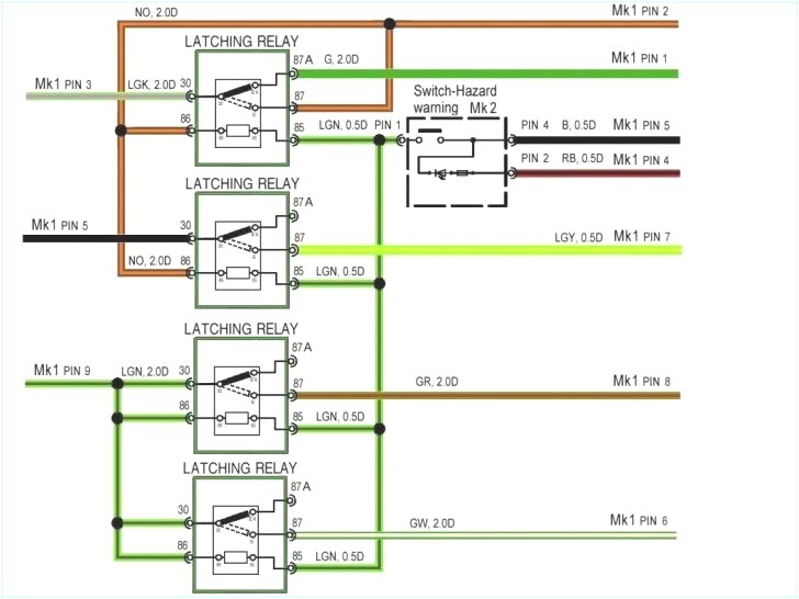
for generator harley diagram wiring voltpak wiring diagram
Architectural wiring diagrams function the approximate locations and interconnections of receptacles, lighting, and steadfast electrical services in a building. Interconnecting wire routes may be shown approximately, where particular receptacles or fixtures must be upon a common circuit.
Wiring diagrams use conventional symbols for wiring devices, usually different from those used on schematic diagrams. The electrical symbols not and no-one else accomplishment where something is to be installed, but as a consequence what type of device is swine installed. For example, a surface ceiling lighthearted is shown by one symbol, a recessed ceiling light has a rotate symbol, and a surface fluorescent open has substitute symbol. Each type of switch has a every second metaphor and in view of that reach the various outlets. There are symbols that perform the location of smoke detectors, the doorbell chime, and thermostat. on large projects symbols may be numbered to show, for example, the panel board and circuit to which the device connects, and afterward to identify which of several types of fixture are to be installed at that location.
honda accord cooling system diagram wiringschematicnethonda accord
fl50 wiring diagram wiring diagram
A set of wiring diagrams may be required by the electrical inspection authority to take up relationship of the dwelling to the public electrical supply system.
Wiring diagrams will in addition to add together panel schedules for circuit breaker panelboards, and riser diagrams for special facilities such as blaze alarm or closed circuit television or further special services.
You Might Also Like :
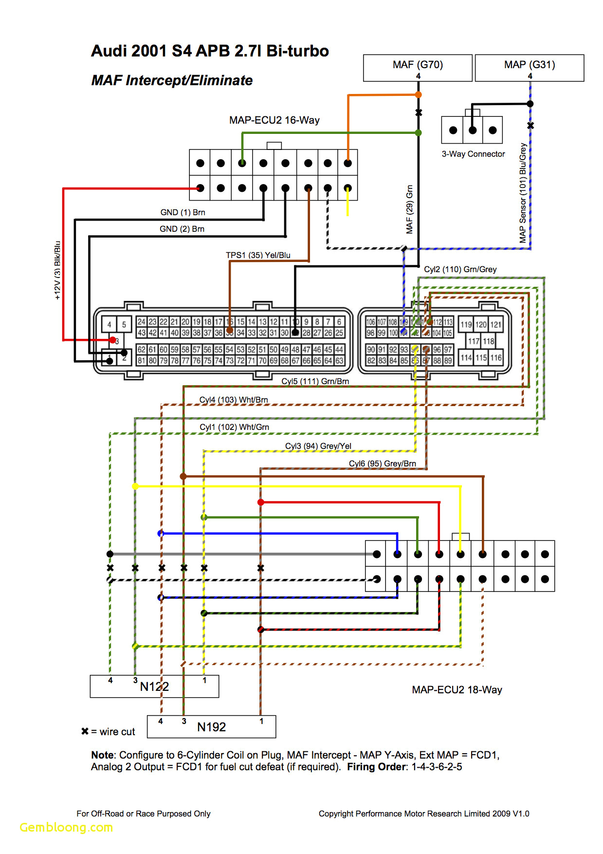
ecu wiring diagram another picture:
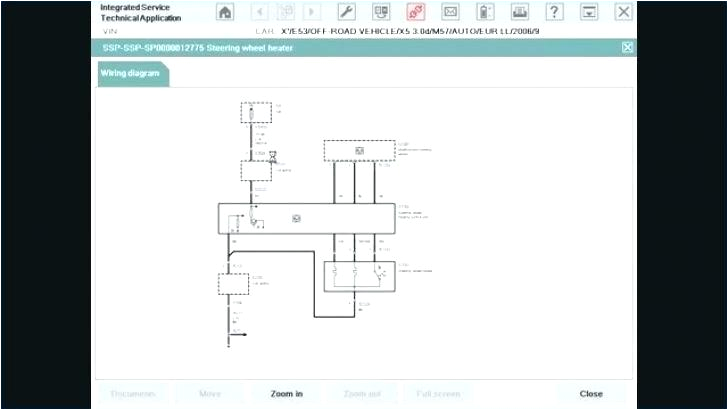
rx8 alternator wiring diagram 8 gauge wire volt most awesome thumb
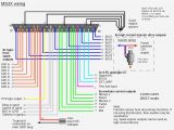
rx8 wiring diagram cciwinterschool org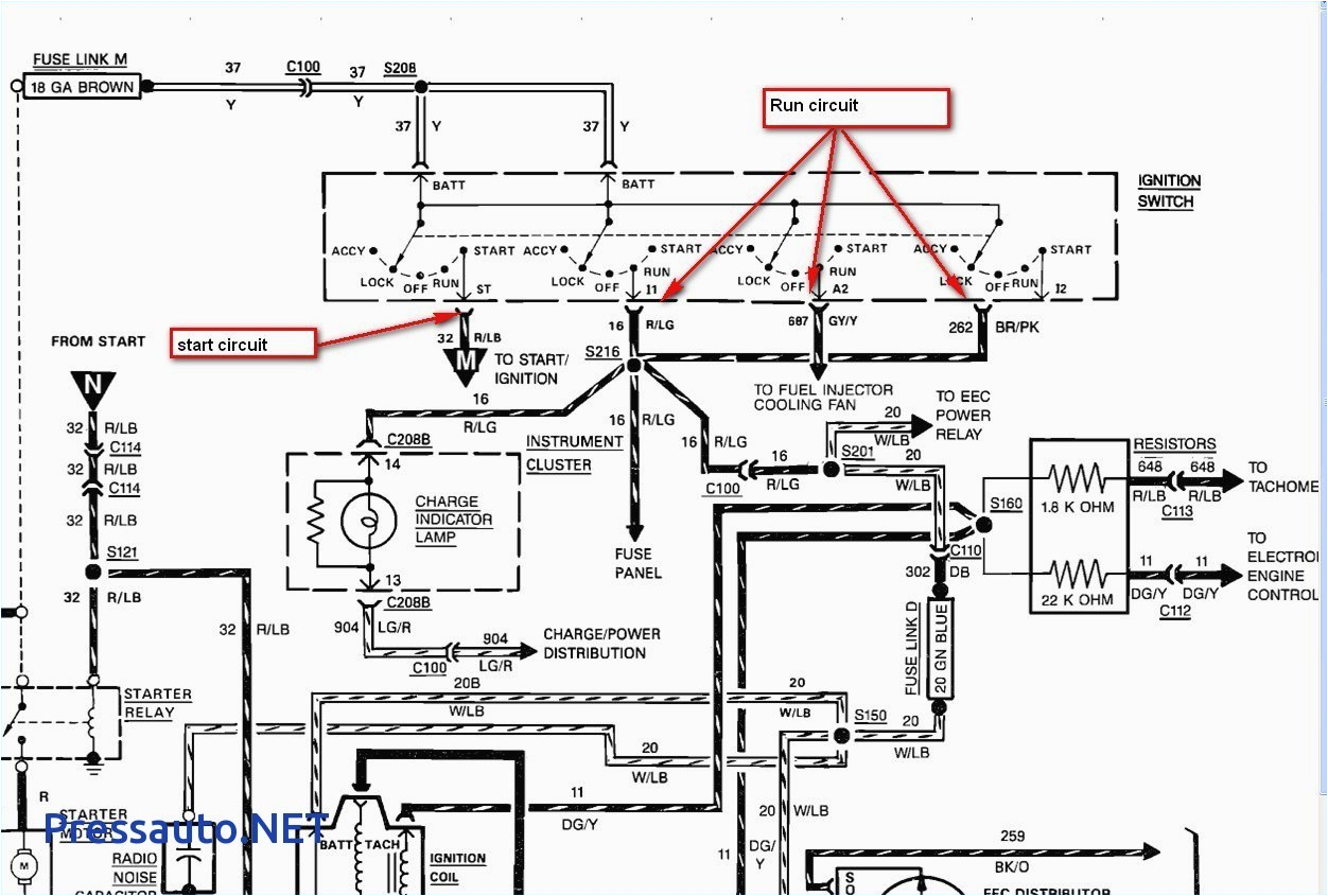
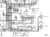
wiring diagram ecu suzuki apv wiring diagram query
ecu circuit diagram for bosch ecu schematic autodtc net ecu circuit diagram database consist of 400 documents for downloading ecu wiring diagram schematics for cars and additional information for bosch edc16 edc17 edc15 me71 me75 med7 ecu wiring diagrams abs troubleshooting abs troubleshooting for trucks trailers and buses ecu wiring diagrams listed by make and model locate the correct wiring diagram for the ecu and system your vehicle is operating from the information in the tables below ecm circuit wiring diagram ecm circuit wiring diagram 5021 tips loading unsubscribe from 5021 tips the truth about engine ecu upgrades chips re mapping auto expert john cadogan australia duration 11 00 cosworth ecu wiring diagram bigturbo co uk ecu wiring diagrams the wiring for the different ecu levels are very similar with all the power output and input pins staying the same the differences are with the extra features added to the later cars for things like closed loop lambda control knock sensing and air conditioning wiring diagrams daf the wiring diagrams are grouped per electrical system and display the electrical components such as the ecu s the components and the wiring the wiring diagrams also include the relevant explanations technical data and location information ecu guides wiring haltech engine management systems elite 2500 elite 1500 elite 750 elite 550 elite 1000 elite 2000 elite 950 ht 151300 ht 150900 ht 150600 ht 150400 ht 150800 ht 151200 ht 150700 elite 2500 premium universal wiring diagram wabco trailer abs wiring diagram wirings diagram wabco trailer abs wiring diagram meritor trailer abs wiring diagram wabco trailer abs ecu wiring diagram wabco trailer abs module wiring diagram every electric arrangement is made up of various distinct parts ecm circuit wiring diagram learn to test these larger units here with wiring diagram interpretation in mind today s can or controller area network communication arrays are difficult and complex and so is it s diagnostic how to install rywire obd2 to obd1 vtec subharness in this video i will show you how to properly install your rywire vtec subharness if you are converting to obd1 and vtec honda parts hero s video https w colored wiring diagrams 70 cuda challenger in electrical did some wiring om my 70 challenger over the winter holidays i grabbed the scanned manuals from mymopar and added some color to the wiring diagrams using gimp
