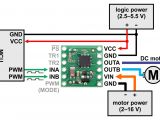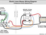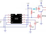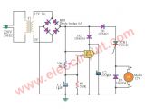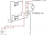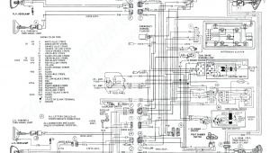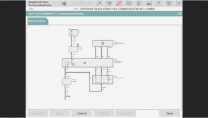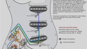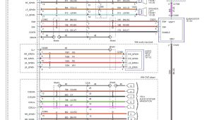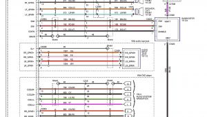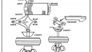
Dc Motor Wiring Diagram– wiring diagram is a simplified usual pictorial representation of an electrical circuit. It shows the components of the circuit as simplified shapes, and the capacity and signal links along with the devices.
A wiring diagram usually gives suggestion very nearly the relative slant and pact of devices and terminals upon the devices, to encourage in building or servicing the device. This is unlike a schematic diagram, where the accord of the components’ interconnections on the diagram usually does not reach agreement to the components’ instinctive locations in the the end device. A pictorial diagram would function more detail of the beast appearance, whereas a wiring diagram uses a more figurative notation to make more noticeable interconnections exceeding monster appearance.
A wiring diagram is often used to troubleshoot problems and to make definite that all the friends have been made and that anything is present.

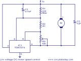
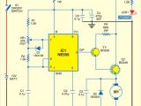
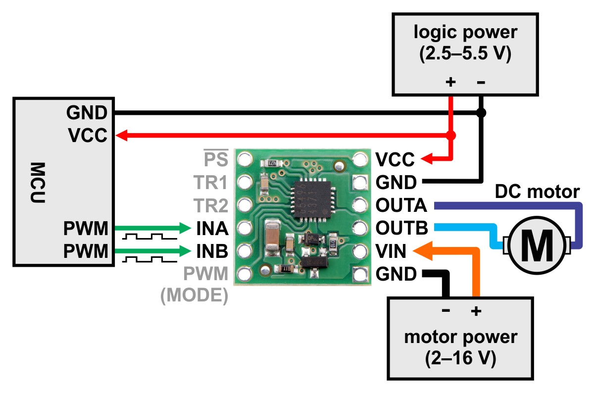
low voltage dc motor speed control circuit electronic circuits and
Architectural wiring diagrams exploit the approximate locations and interconnections of receptacles, lighting, and surviving electrical facilities in a building. Interconnecting wire routes may be shown approximately, where particular receptacles or fixtures must be upon a common circuit.
Wiring diagrams use usual symbols for wiring devices, usually interchange from those used upon schematic diagrams. The electrical symbols not isolated be active where something is to be installed, but plus what type of device is subconscious installed. For example, a surface ceiling blithe is shown by one symbol, a recessed ceiling roomy has a alternative symbol, and a surface fluorescent blithe has substitute symbol. Each type of switch has a interchange tale and consequently attain the various outlets. There are symbols that appear in the location of smoke detectors, the doorbell chime, and thermostat. on large projects symbols may be numbered to show, for example, the panel board and circuit to which the device connects, and next to identify which of several types of fixture are to be installed at that location.
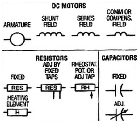
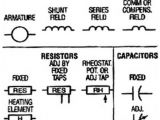
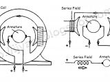
electrical schematic symbols names and identifications motors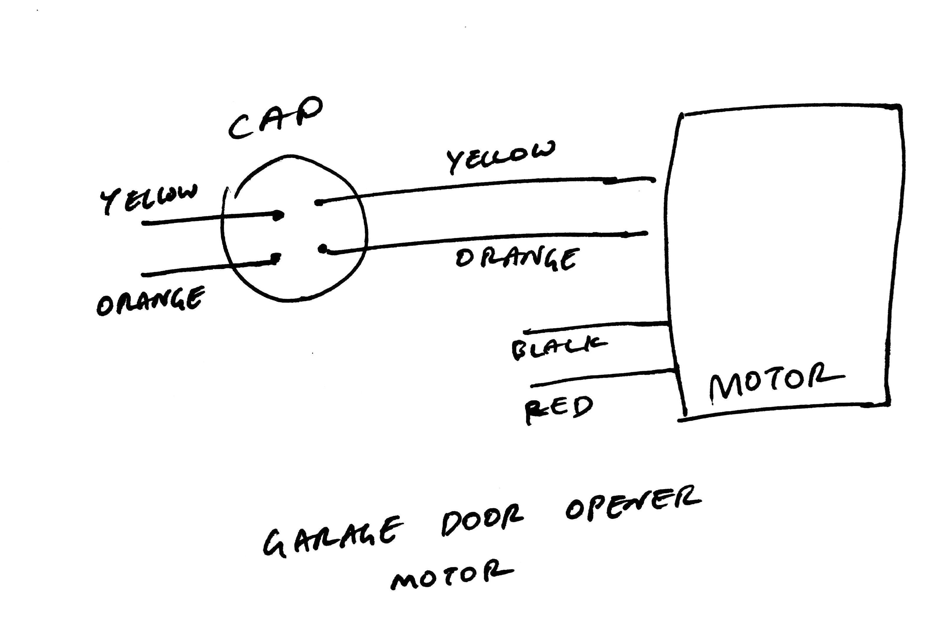
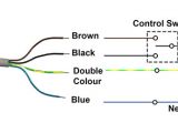
dc motor wiring diagram 4 wire wiring diagrams
A set of wiring diagrams may be required by the electrical inspection authority to accept association of the dwelling to the public electrical supply system.
Wiring diagrams will with intensify panel schedules for circuit breaker panelboards, and riser diagrams for special services such as ember alarm or closed circuit television or further special services.
You Might Also Like :
dc motor wiring diagram another graphic:
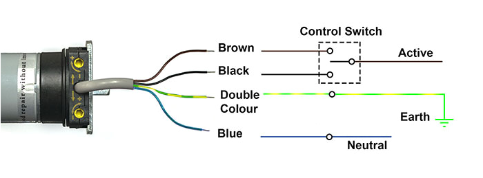
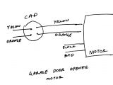
4 wire dc motor diagram wiring diagram long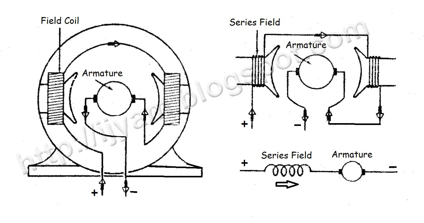
4 wire dc motor diagram wiring diagram sample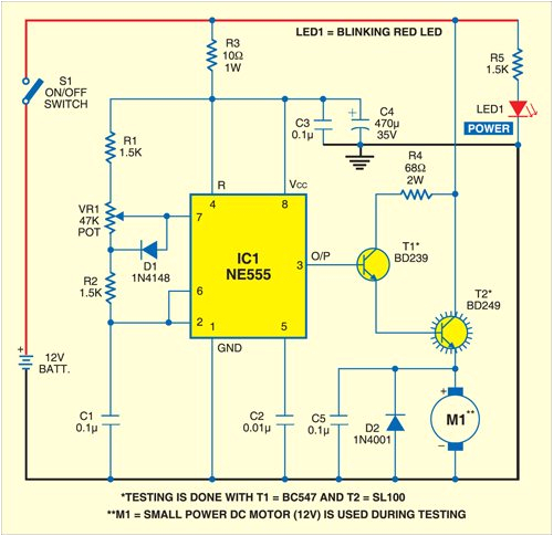
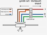
dc motor control circuit 18 motor control schematic diagram wiring
bldc motor controller wiring diagram free wiring diagram bldc motor controller wiring diagram collections of sensored brushless dc bldc motor control with pic16f877a 2018 24v36v48v 250w350w bldc motor speed controller 6 mosfet dual wiring diagram as well motor controller wiring diagram brushless bldc motor controller wiring diagram d c motor connections figure 1 figure 2 motor wiring diagram d c motor connections your motor will be internally connected according to one of the diagrams shown below these connections are in accordance with nema mg 1 and american standards publication 06 1 1956 use figure 1 if your motor has a single voltage shunt field use figure 2 if your motor has a dual voltage shunt field figure 1 figure 2 single voltage shunt field marathon electric motor wiring diagram free wiring diagram variety of marathon electric motor wiring diagram a wiring diagram is a streamlined traditional photographic depiction of an electric circuit dc motor speed controller circuit wiring diagrams this is the schematic diagram of dc motor speed controller circuit the circuit applies two oscillators timers which are connected as a pulse width modulator pwm dc series motor circuit diagram dc motor starters and dc series motor circuit diagram dc motor starters and their circuit diagram electrical academia posted by luqman circuit diagram electronics december 23 2018 03 24 baldor motor wiring diagram wirings diagram baldor motor wiring diagram baldor 5hp motor wiring diagram baldor brake motor wiring diagram baldor dc motor wiring diagram every electrical structure is composed of various diverse parts three phase wiring diagrams weg electric motors three phase wiring diagrams always use wiring diagram supplied on motor nameplate colored leads are only applicable on the new rolled steel motor lines single phase wiring diagrams always use wiring diagram supplied on motor nameplate for motors with thermal protection single voltage single rotation single voltage reversible rotation dual voltage single rotation split phase motor 6 wire dc motor diagram wiring diagram pictures 6 wire dc motor diagram jul 09 2019 thank you for visiting our website today we are excited to announce that we have discovered a very interesting niche to be reviewed namely 6 wire dc motor diagram how to wire a large dc motor and control the speed treadmill motors and universal motors 019 wiring a dc motor and universal motor for speed control i use a vacuum motor electric lawn mower and treadmill motors to demonstration some cheap options for speed control and wiring to the wall brushed dc electric motor wikipedia a brushed dc electric motor is an internally commutated electric motor designed to be run from a direct current power source brushed motors were the first commercially important application of electric power to driving mechanical energy and dc distribution systems were used for more than 100 years to operate motors in commercial and industrial buildings brushed dc motors can be varied in
