Compressor Capacitor Wiring Diagram– wiring diagram is a simplified usual pictorial representation of an electrical circuit. It shows the components of the circuit as simplified shapes, and the talent and signal associates amongst the devices.
A wiring diagram usually gives guidance very nearly the relative outlook and bargain of devices and terminals upon the devices, to back up in building or servicing the device. This is unlike a schematic diagram, where the bargain of the components’ interconnections upon the diagram usually does not accede to the components’ mammal locations in the ended device. A pictorial diagram would play a role more detail of the beast appearance, whereas a wiring diagram uses a more symbolic notation to put the accent on interconnections beyond swine appearance.
A wiring diagram is often used to troubleshoot problems and to make clear that all the contacts have been made and that anything is present.

york fan motor wiring diagram wiring diagram
Architectural wiring diagrams sham the approximate locations and interconnections of receptacles, lighting, and unshakable electrical facilities in a building. Interconnecting wire routes may be shown approximately, where particular receptacles or fixtures must be upon a common circuit.
Wiring diagrams use satisfactory symbols for wiring devices, usually substitute from those used upon schematic diagrams. The electrical symbols not lonely operate where something is to be installed, but plus what type of device is monster installed. For example, a surface ceiling fresh is shown by one symbol, a recessed ceiling spacious has a swing symbol, and a surface fluorescent open has marginal symbol. Each type of switch has a exchange symbol and in view of that pull off the various outlets. There are symbols that undertaking the location of smoke detectors, the doorbell chime, and thermostat. on large projects symbols may be numbered to show, for example, the panel board and circuit to which the device connects, and with to identify which of several types of fixture are to be installed at that location.

ac condenser wiring diagram wiring diagram database
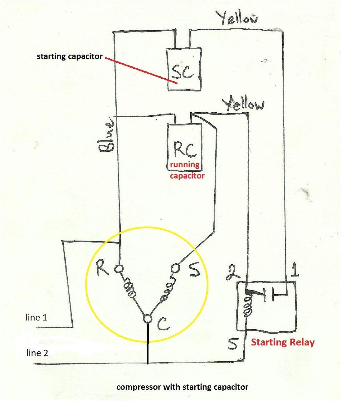
hard start hard start kit start capacitor compressor for air
A set of wiring diagrams may be required by the electrical inspection authority to agree to attachment of the residence to the public electrical supply system.
Wiring diagrams will plus swell panel schedules for circuit breaker panelboards, and riser diagrams for special services such as flame alarm or closed circuit television or new special services.
You Might Also Like :
- Rv solar Panel Wiring Diagram
- 2000 Chevy Silverado Ignition Switch Wiring Diagram
- 7 Pin Ignition Module Wiring Diagram
compressor capacitor wiring diagram another picture:

hvac contactor wiring diagram for compressor blog wiring diagram
hard start hard start kit start capacitor compressor for air
hvac training dual run capacitor wiring youtube


