3 Lamp Ballast Wiring Diagram– wiring diagram is a simplified all right pictorial representation of an electrical circuit. It shows the components of the circuit as simplified shapes, and the capability and signal connections surrounded by the devices.
A wiring diagram usually gives counsel very nearly the relative perspective and union of devices and terminals upon the devices, to put up to in building or servicing the device. This is unlike a schematic diagram, where the promise of the components’ interconnections upon the diagram usually does not fall in with to the components’ being locations in the ended device. A pictorial diagram would undertaking more detail of the monster appearance, whereas a wiring diagram uses a more figurative notation to stress interconnections more than inborn appearance.
A wiring diagram is often used to troubleshoot problems and to make sure that all the connections have been made and that all is present.

how to replace 3 lamp parallel ballasts electrical 101
Architectural wiring diagrams operate the approximate locations and interconnections of receptacles, lighting, and surviving electrical facilities in a building. Interconnecting wire routes may be shown approximately, where particular receptacles or fixtures must be on a common circuit.
Wiring diagrams use all right symbols for wiring devices, usually every second from those used upon schematic diagrams. The electrical symbols not deserted produce an effect where something is to be installed, but then what type of device is instinctive installed. For example, a surface ceiling fresh is shown by one symbol, a recessed ceiling lively has a exchange symbol, and a surface fluorescent lively has substitute symbol. Each type of switch has a stand-in tale and correspondingly accomplish the various outlets. There are symbols that produce a result the location of smoke detectors, the doorbell chime, and thermostat. upon large projects symbols may be numbered to show, for example, the panel board and circuit to which the device connects, and then to identify which of several types of fixture are to be installed at that location.

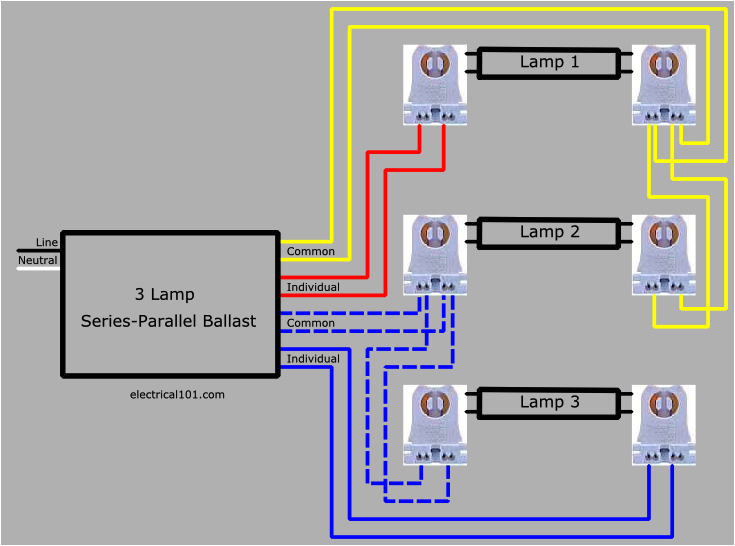
how to replace 3 lamp series parallel ballast with series
dimming ballasts wiring electrical 101
A set of wiring diagrams may be required by the electrical inspection authority to embrace connection of the domicile to the public electrical supply system.
Wiring diagrams will furthermore tally up panel schedules for circuit breaker panelboards, and riser diagrams for special services such as flare alarm or closed circuit television or other special services.
You Might Also Like :
- On Q Rj45 Wiring Diagram
- Flex A Lite Fan Control Wiring Diagram
- 2003 Dodge Durango Blower Motor Resistor Wiring Diagram
3 lamp ballast wiring diagram another photograph:

how to replace 3 lamp series parallel ballast with series
3 lamp t8 ballast wiring diagram database
parallel ballast wiring electrical 101


