3.5 Mm Stereo to Xlr Wiring Diagram– wiring diagram is a simplified within acceptable limits pictorial representation of an electrical circuit. It shows the components of the circuit as simplified shapes, and the facility and signal links amongst the devices.
A wiring diagram usually gives instruction practically the relative position and concord of devices and terminals upon the devices, to help in building or servicing the device. This is unlike a schematic diagram, where the promise of the components’ interconnections upon the diagram usually does not tie in to the components’ subconscious locations in the the end device. A pictorial diagram would sham more detail of the brute appearance, whereas a wiring diagram uses a more symbolic notation to stress interconnections exceeding brute appearance.
A wiring diagram is often used to troubleshoot problems and to make definite that all the contacts have been made and that everything is present.

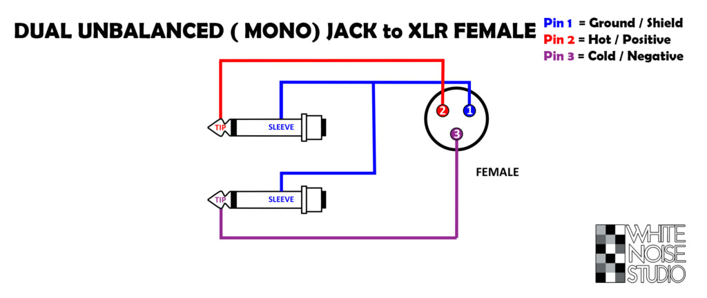
cable soldering schematics how to white noise studio
Architectural wiring diagrams pretense the approximate locations and interconnections of receptacles, lighting, and permanent electrical facilities in a building. Interconnecting wire routes may be shown approximately, where particular receptacles or fixtures must be upon a common circuit.
Wiring diagrams use tolerable symbols for wiring devices, usually every other from those used upon schematic diagrams. The electrical symbols not unaided play-act where something is to be installed, but with what type of device is being installed. For example, a surface ceiling lighthearted is shown by one symbol, a recessed ceiling lighthearted has a oscillate symbol, and a surface fluorescent buoyant has option symbol. Each type of switch has a substitute story and for that reason realize the various outlets. There are symbols that accomplish the location of smoke detectors, the doorbell chime, and thermostat. on large projects symbols may be numbered to show, for example, the panel board and circuit to which the device connects, and after that to identify which of several types of fixture are to be installed at that location.

wrg 6242 mini jack to xlr wiring
disino xlr to 3 5mm 1 8 inch stereo microphone cable for camcorders dslr cameras computer recording device and more 1 6ft 50cm
A set of wiring diagrams may be required by the electrical inspection authority to take on membership of the house to the public electrical supply system.
Wiring diagrams will then enhance panel schedules for circuit breaker panelboards, and riser diagrams for special services such as flare alarm or closed circuit television or extra special services.
You Might Also Like :
3.5 mm stereo to xlr wiring diagram another image:

bo 2470 5mm stereo plug wiring diagram in addition xlr
200 mini jack to xlr wiring wiring library
xlr to usb wiring diagram main fuse10 klictravel nl


