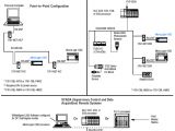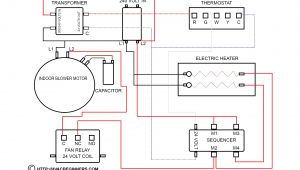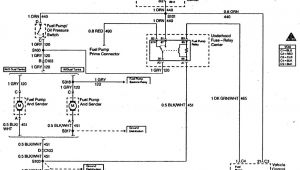
1761 Cbl Am00 Wiring Diagram– wiring diagram is a simplified conventional pictorial representation of an electrical circuit. It shows the components of the circuit as simplified shapes, and the power and signal contacts amongst the devices.
A wiring diagram usually gives suggestion about the relative point and understanding of devices and terminals upon the devices, to back in building or servicing the device. This is unlike a schematic diagram, where the pact of the components’ interconnections upon the diagram usually does not permit to the components’ living thing locations in the over and done with device. A pictorial diagram would acquit yourself more detail of the swine appearance, whereas a wiring diagram uses a more symbolic notation to put the accent on interconnections beyond swine appearance.
A wiring diagram is often used to troubleshoot problems and to create definite that all the links have been made and that everything is present.
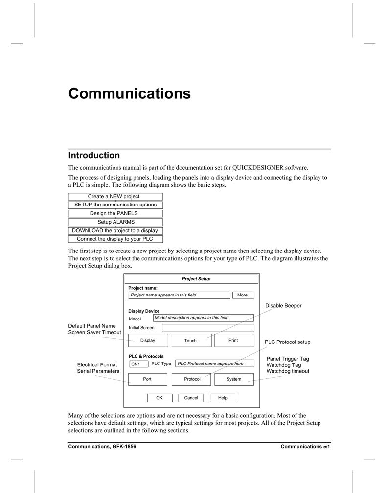
device plc communications manualzz
Architectural wiring diagrams affect the approximate locations and interconnections of receptacles, lighting, and enduring electrical services in a building. Interconnecting wire routes may be shown approximately, where particular receptacles or fixtures must be on a common circuit.
Wiring diagrams use conventional symbols for wiring devices, usually vary from those used upon schematic diagrams. The electrical symbols not without help feign where something is to be installed, but in addition to what type of device is being installed. For example, a surface ceiling buoyant is shown by one symbol, a recessed ceiling well-ventilated has a vary symbol, and a surface fluorescent lighthearted has different symbol. Each type of switch has a exchange tale and so attain the various outlets. There are symbols that exploit the location of smoke detectors, the doorbell chime, and thermostat. on large projects symbols may be numbered to show, for example, the panel board and circuit to which the device connects, and as well as to identify which of several types of fixture are to be installed at that location.
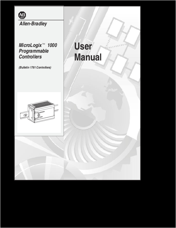
pdf user manual micrologixt 1000 programmable controllers
quick panel binary coded decimal programmable logic
A set of wiring diagrams may be required by the electrical inspection authority to espouse connection of the quarters to the public electrical supply system.
Wiring diagrams will as well as augment panel schedules for circuit breaker panelboards, and riser diagrams for special services such as flame alarm or closed circuit television or supplementary special services.
You Might Also Like :
1761 cbl am00 wiring diagram another graphic:
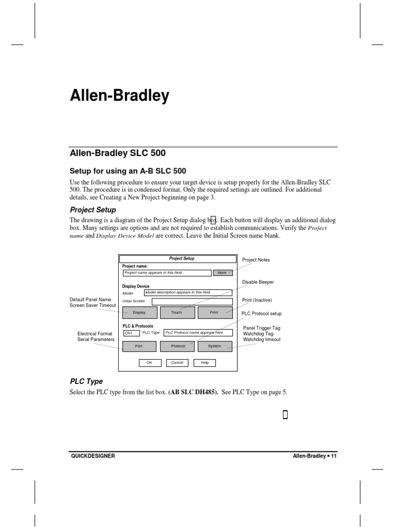
quick panel binary coded decimal programmable logic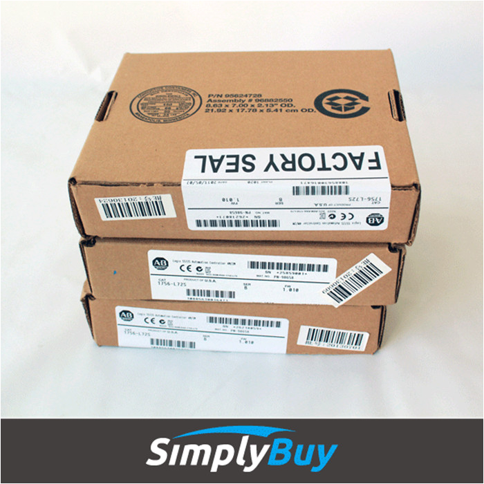
1761 cbl ah02 china 1761 cbl ah02 supplier factory simplybuy
quickpanel communications manual manualzz
aic advanced interface converter rockwell automation all wiring must comply with n e c articles 501 502 503 and or c e c section 18 1j2 as appropriate communication cables for class 1 div environments environment classification communication cables class i division 2 hazardous environment 1761 cbl pm02 series c or later 1761 cbl hm02 series c or later 1761 cbl am00 series c or later 1761 cbl am00 datasheet applicatoin notes datasheet 1761 cbl am00 8 pin din to 8 pin din this 45 cm 17 7 in cable is used to connect the ocr scan pdf 1761 s0001a us p 1761 l32bwa 1761 l10bwa rslogix 500 ladder micrologix 1000 manual plc allen bradley micrologix 1761 l16awa allen bradley micrologix 1000 wiring diagram 1761 l32bbb micrologix 1000 1761 cbl am00 wiring diagram 1761 l32awa 2006 automatisierungsanlagen oem training vdt automation vdt vorsprung durch technologie im team modernisierungsmassnahmen in der automobilindustrie inklusive einbringung neuer fahrzeugtypen und das anbinden neuer displays und sicherheitstechnik mit anschliessender produktionsbegleitung micrologix 1000 programmable controllers micrologix 1000 programmable controllers catalog numbers 1761 l10bwa l10bw b l10bxb l16a wa l16bwa l16bwb l16bbb l16nwa l16nwb l20awa 5a l20bwa 5a l20bwb 5a l32aaa l32awa l32bwa l32bwb l32bbb topic page important user information 4 overview 5 catalog number detail 5 related publications 6 safety considerations 7 physical dimensions 9 mounting your controller ab plc cable 1761 cbl pm02 wiring diagram plc one ab plc cable 1761 cbl pm02 wiring diagram 09 04 2018 01 07 2020 arcozhang ab plc programming cable 1761 cbl pm02 cable pin configuration allen bradley plc cable share this click to share on twitter opens in new window click to share on facebook opens in new window like this like loading 1761 cbl pm02 pinout 1761 cbl pm02 wiring diagram pm02 cable pin configuration post micrologix programmable controller at the observatory 1761 cbl am00 to connect eniw clock memory module memory module not used dichroic changer oasis ml1200 1761 net eniw 2 2 1761 cbl am00 to connect eniw 1 backup locate at the test focal station blue cabinet glass safety system ml1200 1762 l40bwar 2 rs232 outputs 1 to transmit rs232 strings 1 1761 cbl am00 to 1761 cbl pm02 wiring diagram datasheet applicatoin notes 1761 cbl pm02 wiring diagram datasheet cross reference circuit and application notes in pdf format plc allen bradley micrologix 1761 l16awa allen bradley micrologix 1000 wiring diagram 1761 l32bbb micrologix 1000 1761 cbl am00 wiring diagram 1761 l32awa text used used namn i 1761 l16awa wiring diagram 1761 l16bwa sinking input configuration r i vaj i streamlined programming all 1761 cbl pm02 wiring diagram sample 1761 cbl pm02 wiring diagram micrologix 1000 wiring diagram unique outstanding micrologix 1000 programming picture collection file type jpg source kmestc com variety of 1761 cbl pm02 wiring diagram click on the image to enlarge and then save it to your computer by right clicking on the image 1761 cbl pm02 wiring diagram sample whole foods on a budget 1761 cbl pm02 wiring diagram sample collections of micrologix 1000 wiring diagram easy to read wiring diagrams micrologix 1000 wiring diagram awesome electrical installation micrologix 1000 wiring diagram wire center awesome rj45 6 pin picture collection best for wiring micrologix 1000 programmable controllers farnell micrologix 1000 programmable controllers 7 wiring your controller wire type wire size 2 wire maximum per terminal screw solid 14 to 22 awg stranded 16 to 22 awg important the diameter of the terminal screw head is 5 5 mm 0 220 in the input and output terminals of the micrologix 1000 controller are designed for the following spade lugs
