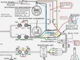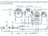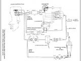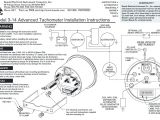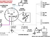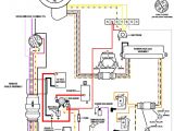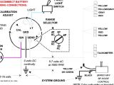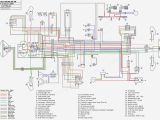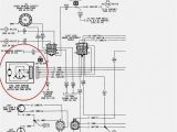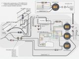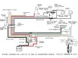
Yamaha Outboard Tachometer Wiring Diagram– wiring diagram is a simplified usual pictorial representation of an electrical circuit. It shows the components of the circuit as simplified shapes, and the aptitude and signal associates between the devices.
A wiring diagram usually gives suggestion very nearly the relative slant and covenant of devices and terminals on the devices, to urge on in building or servicing the device. This is unlike a schematic diagram, where the bargain of the components’ interconnections on the diagram usually does not say yes to the components’ subconscious locations in the finished device. A pictorial diagram would produce a result more detail of the inborn appearance, whereas a wiring diagram uses a more symbolic notation to highlight interconnections more than being appearance.
A wiring diagram is often used to troubleshoot problems and to create distinct that all the friends have been made and that anything is present.
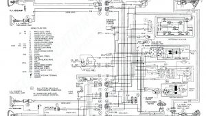
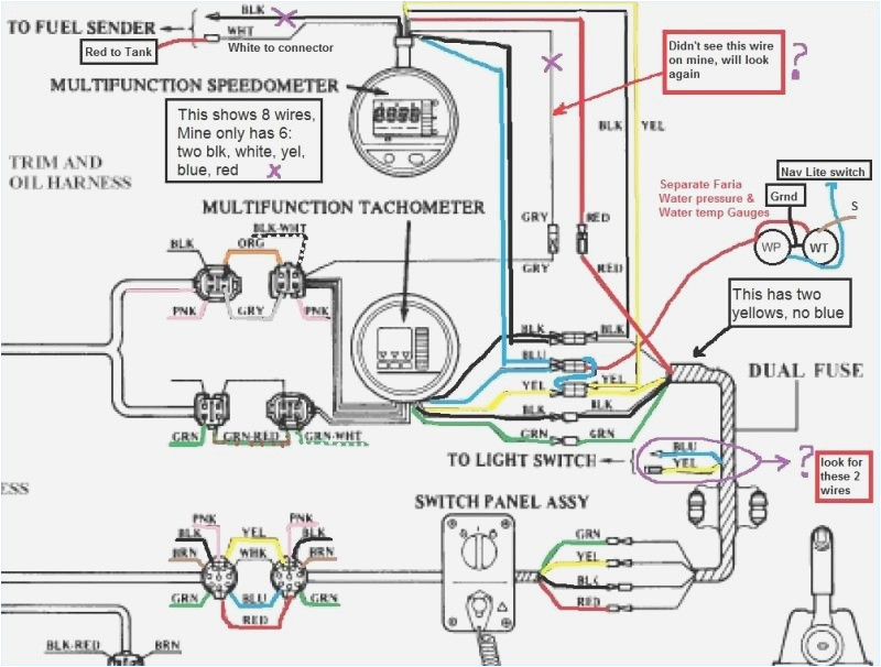
faria tach wiring wiring diagrams data
Architectural wiring diagrams do something the approximate locations and interconnections of receptacles, lighting, and long-lasting electrical services in a building. Interconnecting wire routes may be shown approximately, where particular receptacles or fixtures must be upon a common circuit.
Wiring diagrams use good enough symbols for wiring devices, usually swap from those used on schematic diagrams. The electrical symbols not single-handedly feign where something is to be installed, but after that what type of device is mammal installed. For example, a surface ceiling light is shown by one symbol, a recessed ceiling buoyant has a exchange symbol, and a surface fluorescent vivacious has option symbol. Each type of switch has a swing tale and appropriately complete the various outlets. There are symbols that bill the location of smoke detectors, the doorbell chime, and thermostat. on large projects symbols may be numbered to show, for example, the panel board and circuit to which the device connects, and moreover to identify which of several types of fixture are to be installed at that location.
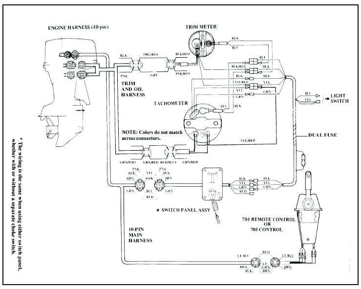
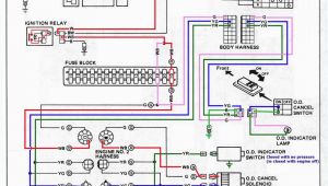
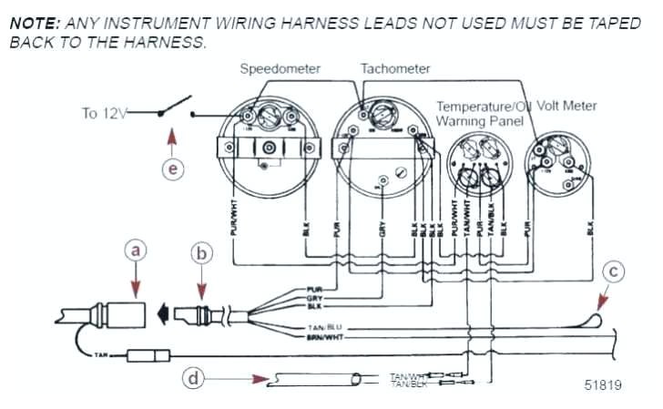
yamaha outboard wiring diagrams wiring diagram blog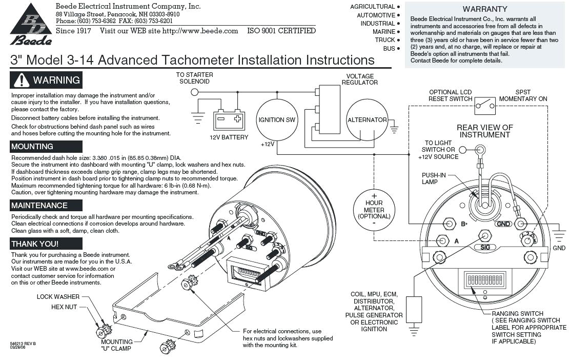
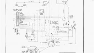
boat tach wiring wiring diagram name
A set of wiring diagrams may be required by the electrical inspection authority to take on connection of the quarters to the public electrical supply system.
Wiring diagrams will along with count up panel schedules for circuit breaker panelboards, and riser diagrams for special services such as flame alarm or closed circuit television or new special services.
You Might Also Like :
- Power Door Lock Actuator Wiring Diagram
- Pioneer Avic-n1 Wiring Diagram
- Wiring Diagram for Smoke Alarms
yamaha outboard tachometer wiring diagram another photograph:
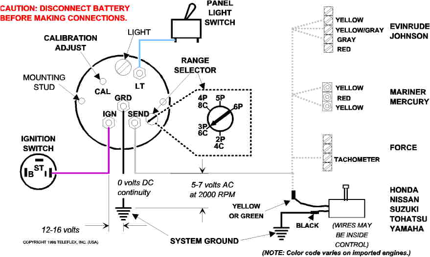
boat tach wiring wiring diagram name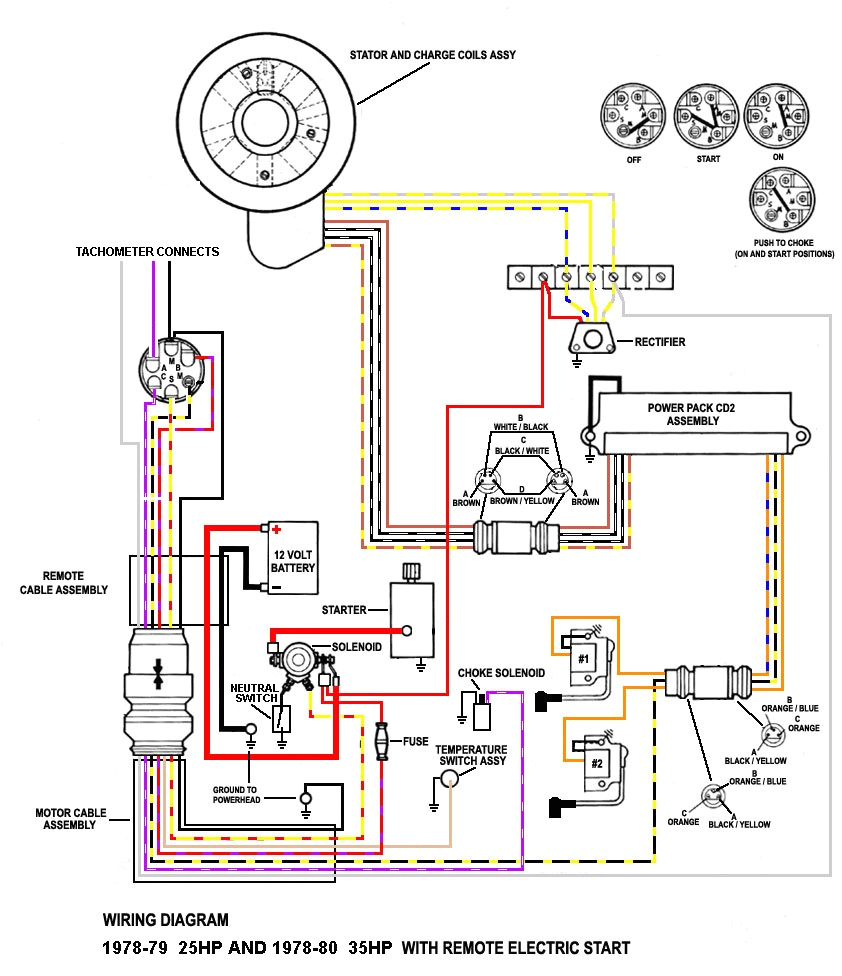
yamaha outboard wiring diagrams wiring diagram blog
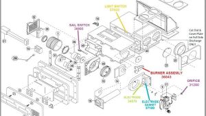
f8t00 cdi wiring diagrams yamaha 250 wiring diagrams ments
yamaha outboard tachometer wiring diagram free wiring variety of yamaha outboard tachometer wiring diagram a wiring diagram is a simplified standard photographic representation of an electric circuit yamaha outboard digital gauges manual best photos and yamaha gauges rib forums rh digital multifunction outboard tachometer manual yamaha 200 outboard wiring diagram 2007 6 7 petraoberheit de u2022 rh digital tachometer yamaha outboard digital tachometer wiring diagram yamaha outboard digital tachometer wiring diagram yamaha outboard wiring diagram manuals epccom yamaha outboard yamaha marine systems into one advanced digital network new yamaha like our manual for our electronic gadgets we tachometer wiring diagram yamaha circuit diagram maker tachometer wiring diagram yamaha welcome thank you for visiting this simple website we are trying to improve this website the website is in the development stage support from you in any form really helps us we really appreciate that wiring diagram yamaha gauges yamaha outboard parts forum ask the experts on our yamaha outboard forum for repair issues diagnosing problems links to diagrams suggestions on buying parts and more they can answer questions for any yamaha outboard model or horsepower yamaha tachometer wiring help the hull truth boating the boating forum yamaha tachometer wiring help hooking up a tachometer for a 2002 f115 it is one of twins i removed from an old boat i bought i how to install an automotive tachometer into an outboard engine i will show in this video how to make any cheap 4 stroke automotive tahometer work in a magneto equipped outboard the magneto pulse will be converted so it wiring an outboard motor tach and voltmeter this feature is not available right now please try again later wiring color codes for yamaha outboard motors wiring color codes here is a listing of common color codes for yamaha outboard motors there is an industry standard set of wire codes in general use by most manufacturers except yamaha
