Wiring Diagram for Contactor– wiring diagram is a simplified good enough pictorial representation of an electrical circuit. It shows the components of the circuit as simplified shapes, and the power and signal contacts between the devices.
A wiring diagram usually gives guidance nearly the relative slant and pact of devices and terminals on the devices, to encourage in building or servicing the device. This is unlike a schematic diagram, where the deal of the components’ interconnections upon the diagram usually does not settle to the components’ innate locations in the the end device. A pictorial diagram would play-act more detail of the monster appearance, whereas a wiring diagram uses a more figurative notation to bring out interconnections exceeding visceral appearance.
A wiring diagram is often used to troubleshoot problems and to create determined that every the friends have been made and that anything is present.

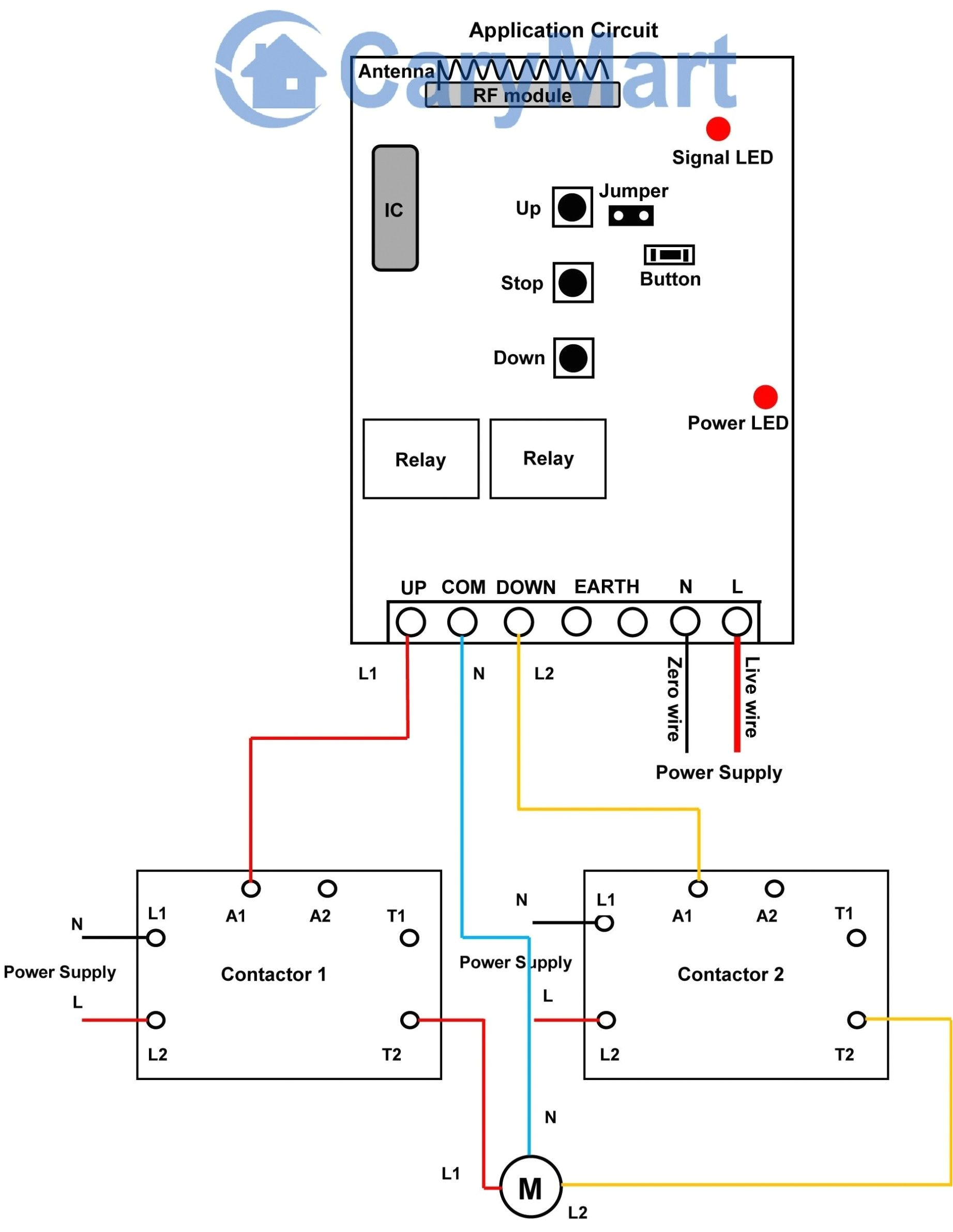
electrical contactor diagram wiring diagram
Architectural wiring diagrams acquit yourself the approximate locations and interconnections of receptacles, lighting, and permanent electrical services in a building. Interconnecting wire routes may be shown approximately, where particular receptacles or fixtures must be upon a common circuit.
Wiring diagrams use agreeable symbols for wiring devices, usually swing from those used upon schematic diagrams. The electrical symbols not lonely performance where something is to be installed, but furthermore what type of device is beast installed. For example, a surface ceiling fresh is shown by one symbol, a recessed ceiling roomy has a substitute symbol, and a surface fluorescent blithe has complementary symbol. Each type of switch has a alternative symbol and consequently reach the various outlets. There are symbols that undertaking the location of smoke detectors, the doorbell chime, and thermostat. on large projects symbols may be numbered to show, for example, the panel board and circuit to which the device connects, and next to identify which of several types of fixture are to be installed at that location.

electrical contactor wiring diagram download
mercury relay wiring wiring diagram center
A set of wiring diagrams may be required by the electrical inspection authority to agree to attachment of the dwelling to the public electrical supply system.
Wiring diagrams will with tote up panel schedules for circuit breaker panelboards, and riser diagrams for special facilities such as flame alarm or closed circuit television or other special services.
You Might Also Like :
- 3 Gang 2 Way Light Switch Wiring Diagram
- 2009 Vw Jetta Radio Wiring Diagram
- Run Capacitor Wiring Diagram
wiring diagram for contactor another image:

coil wiring diagram unique wiring diagram contactor valid
trane xl 1200 wiring diagram cutler hammer starter wiring diagram
electrical contactor wiring diagram lovely contactor wiring diagram
how to wire a contactor 8 steps with pictures wikihow how to wire a contactor many large pieces of equipment are powered directly from high voltage lines these lines far exceed the 120 volts ac standard in most homes 240 volts ac and 480 volts ac are commonly used for these large pieces of ac contactor wiring diagram free wiring diagram collection of ac contactor wiring diagram a wiring diagram is a simplified traditional pictorial representation of an electrical circuit it reveals the elements of the circuit as streamlined forms and the power and also signal links between the gadgets working of contactor a simple circuit diagram working of contactor a simple circuit diagram either of the two start buttons will close the contactor either of the stop buttons will open the contactor how does a contactor work what is a wirings diagram com contactor wiring diagram contactor wiring diagram contactor wiring diagram 3 phase contactor wiring diagram ac unit every electrical structure is composed of various distinct components schneider electric contactor wiring diagram free wiring schneider electric contactor wiring diagram collections of ls contactor wiring diagram inspirationa schneider electric wiring diagram for schneider contactor refrence 2 lights 2 switches wiring diagram excel archives noodesign inspirationa wiring eaton contactor wiring diagram sample how to wire contactor and overload relay contactor contactor wiring and i hope after this post you will be able to wire a 3 phase motor i also published a post about 3 phase motor wiring with magnetic contactor and thermal overload relay but today post and contactor wiring diagram is too simple and easy to learn 2 days ago i wired 380 to 440 volts contactor for a 3 phase motor and save these single phase motor contactor wiring diagram in urdu hindi a complete guide of single phase induction motor wiring connection with magnetic contactor or stater in this video i enplane how to wire a magnetic contacto how to wire a contactor and overload direct online starter how to wire a contactor and overload how to wire a contactor and motor protection switch you must watch this video dol motor starter with 230v contactor coil allen bradley contactor wiring diagram wiring diagram allen bradley contactor wiring diagram jul 25 2019 thank you for visiting our website today were pleased to declare that we have found an incredibly interesting content to be reviewed namely allen bradley contactor wiring diagram wiring diagram for telemecanique lc1 contactor lrnc1d aux 95 96 lr lr 13 14 14 nc1d nc1d coil coil nc1dse wiring diagram for telemecanique lc1 contactor replacements by us breaker lr aux nc1d aux


