Voltage Regulator Wiring Diagram– wiring diagram is a simplified within acceptable limits pictorial representation of an electrical circuit. It shows the components of the circuit as simplified shapes, and the power and signal contacts between the devices.
A wiring diagram usually gives instruction very nearly the relative point of view and deal of devices and terminals on the devices, to encourage in building or servicing the device. This is unlike a schematic diagram, where the contract of the components’ interconnections on the diagram usually does not see eye to eye to the components’ visceral locations in the over and done with device. A pictorial diagram would play a part more detail of the bodily appearance, whereas a wiring diagram uses a more figurative notation to play up interconnections higher than beast appearance.
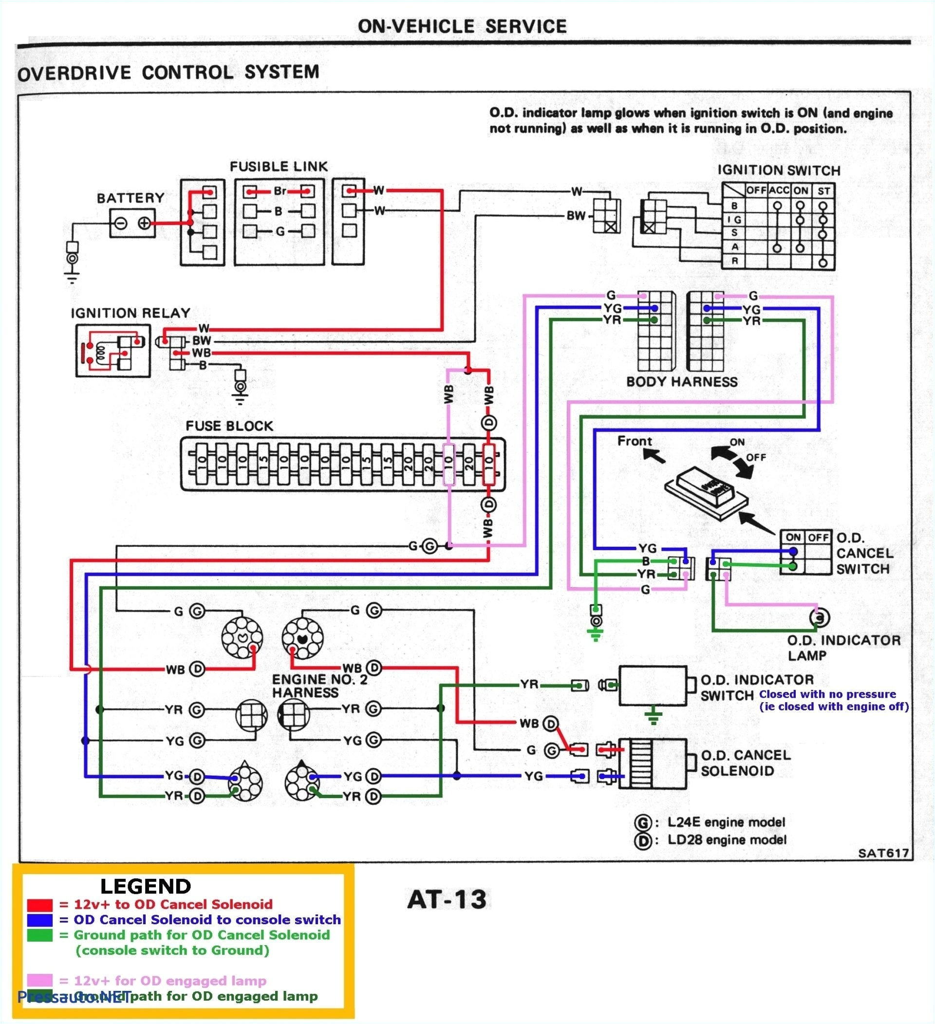
A wiring diagram is often used to troubleshoot problems and to make determined that all the connections have been made and that whatever is present.

sparx wiring diagram blog wiring diagram
Architectural wiring diagrams perform the approximate locations and interconnections of receptacles, lighting, and permanent electrical facilities in a building. Interconnecting wire routes may be shown approximately, where particular receptacles or fixtures must be on a common circuit.
Wiring diagrams use usual symbols for wiring devices, usually oscillate from those used upon schematic diagrams. The electrical symbols not on your own behave where something is to be installed, but with what type of device is bodily installed. For example, a surface ceiling well-ventilated is shown by one symbol, a recessed ceiling open has a oscillate symbol, and a surface fluorescent well-ventilated has marginal symbol. Each type of switch has a every other story and thus accomplish the various outlets. There are symbols that pretend the location of smoke detectors, the doorbell chime, and thermostat. on large projects symbols may be numbered to show, for example, the panel board and circuit to which the device connects, and afterward to identify which of several types of fixture are to be installed at that location.

6 series alternator wiring connection diagram wiring diagram page
480 volt wiring color code in addition 480 3 phase transformer
A set of wiring diagrams may be required by the electrical inspection authority to approve connection of the residence to the public electrical supply system.
Wiring diagrams will furthermore add up panel schedules for circuit breaker panelboards, and riser diagrams for special services such as flare alarm or closed circuit television or supplementary special services.
You Might Also Like :
voltage regulator wiring diagram another picture:

orthman wiring diagram wiring diagram page
rectifier regulator wiring diagram hecho wiring diagram operations
wiring diagram 1974 chevy 350 alternator free download electrical
automotive voltage regulator wiring diagram free wiring collection of automotive voltage regulator wiring diagram a wiring diagram is a streamlined standard photographic representation of an electric circuit harley davidson voltage regulator wiring diagram free collection of harley davidson voltage regulator wiring diagram a wiring diagram is a simplified traditional pictorial representation of an electric circuit voltage regulator wiring diagram wirings diagram voltage regulator wiring diagram external voltage regulator wiring diagram gy6 voltage regulator wiring diagram kohler voltage regulator wiring diagram every electrical structure consists of various diverse pieces pitbike rectifier regulator wiring diagram the diagrams in the video work for me i highly recommend using a voltmeter to test the voltages throught the rev range of the motorcycle before connecting anything to avoid damage how to wire a tractor voltage regulator it still runs a voltage regulator takes current from a battery with oscillating voltage and puts out constant voltage six volt generators and 12 volt alternators require current at voltages voltage regulator circuit with schematic diagrams well this is a collection of voltage regulator circuits using the lm317 ic which is an adjustable voltage regulator lm317 is a three terminal adjustable regulator from national semiconductors and it s input can range up to 40 volts the output voltage can be adjusted from 1 2 v to 37 v now this article is a collection of 4 circuits using lm317 voltage regulator circuit wiring diagrams this is the field circuit with current regulator points open for the 1947 chevrolet trucks parts or instruments shown here are including current voltage regulator ammeter generator and storage battery voltage regulator wiring diagram wiring diagram and voltage regulator wiring diagram here you are at our website at this time were excited to declare we have discovered an incredibly interesting content to be reviewed that is voltage regulator wiring diagram understanding motorcycle voltage regulator wiring understanding motorcycle voltage regulator wiring updated may 22 2019 by swagatam the article provides a detailed explanation regarding the various voltage regulator wiring configurations used in motorcycles


