True bypass Wiring Diagram– wiring diagram is a simplified standard pictorial representation of an electrical circuit. It shows the components of the circuit as simplified shapes, and the facility and signal links with the devices.
A wiring diagram usually gives guidance more or less the relative slant and bargain of devices and terminals upon the devices, to help in building or servicing the device. This is unlike a schematic diagram, where the union of the components’ interconnections on the diagram usually does not correspond to the components’ brute locations in the finished device. A pictorial diagram would take effect more detail of the monster appearance, whereas a wiring diagram uses a more symbolic notation to put the accent on interconnections beyond visceral appearance.
A wiring diagram is often used to troubleshoot problems and to make definite that every the connections have been made and that everything is present.
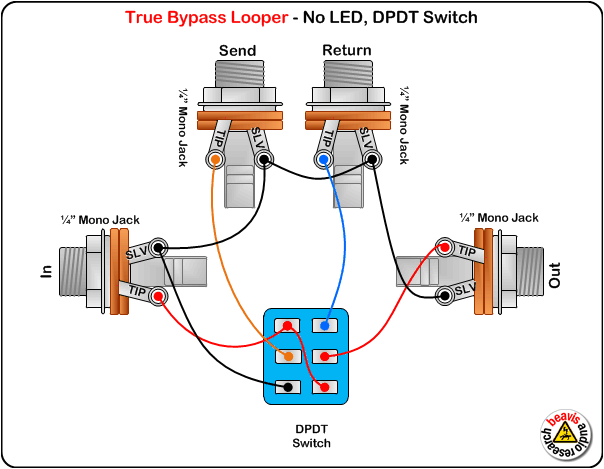
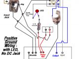
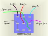
guitar pedal switch wiring diagrams wiring diagrams
Architectural wiring diagrams measure the approximate locations and interconnections of receptacles, lighting, and long-lasting electrical services in a building. Interconnecting wire routes may be shown approximately, where particular receptacles or fixtures must be on a common circuit.
Wiring diagrams use suitable symbols for wiring devices, usually oscillate from those used on schematic diagrams. The electrical symbols not unaided act out where something is to be installed, but next what type of device is subconscious installed. For example, a surface ceiling spacious is shown by one symbol, a recessed ceiling spacious has a swing symbol, and a surface fluorescent blithe has marginal symbol. Each type of switch has a substitute metaphor and correspondingly do the various outlets. There are symbols that be active the location of smoke detectors, the doorbell chime, and thermostat. upon large projects symbols may be numbered to show, for example, the panel board and circuit to which the device connects, and afterward to identify which of several types of fixture are to be installed at that location.
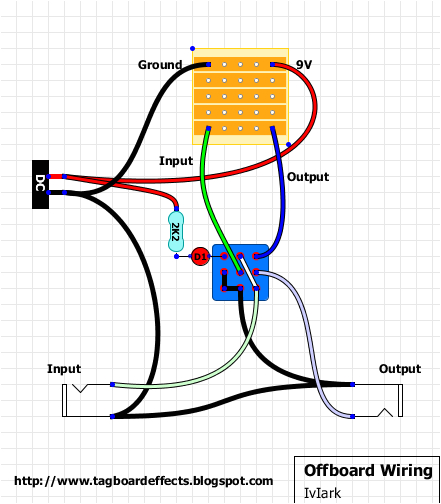
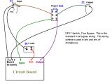
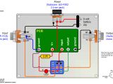
guitar fx layouts offboard wiring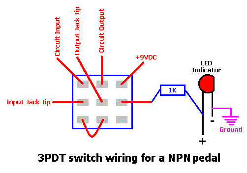
guitar pedal switch wiring diagrams wiring diagrams
A set of wiring diagrams may be required by the electrical inspection authority to implement connection of the house to the public electrical supply system.
Wiring diagrams will moreover include panel schedules for circuit breaker panelboards, and riser diagrams for special services such as flare alarm or closed circuit television or new special services.
You Might Also Like :
true bypass wiring diagram another graphic:
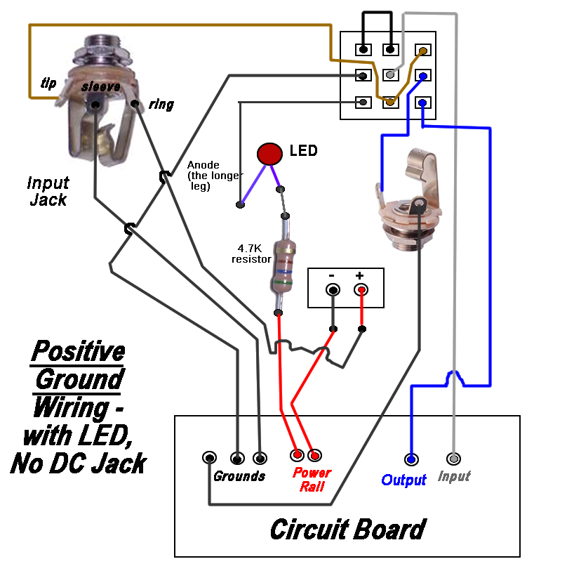
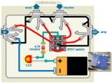
guitar pedal wiring diagram wiring diagram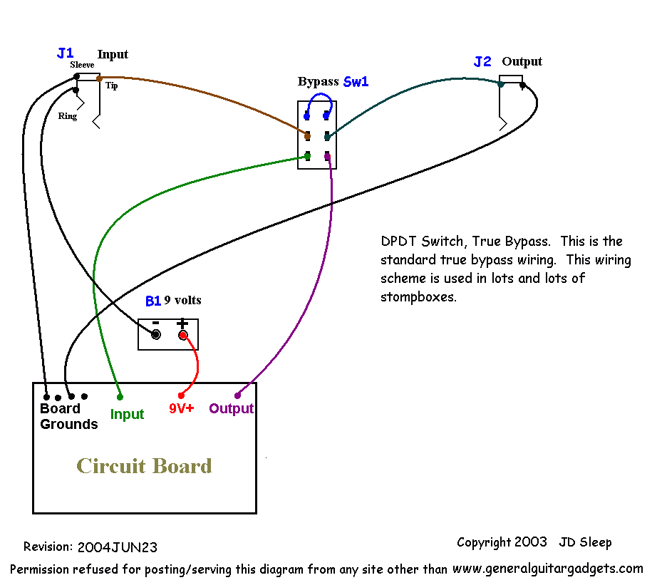
guitar pedal switch wiring diagrams wiring diagrams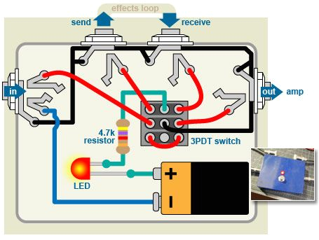
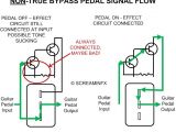
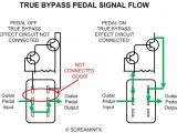
diagram bypass pedal wiring fx circuits guitar guitar diy
