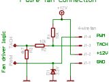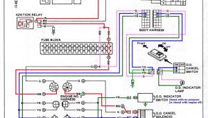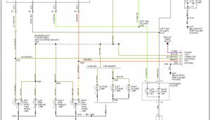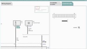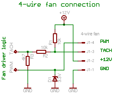
Tiny Pwm Wiring Diagram– wiring diagram is a simplified good enough pictorial representation of an electrical circuit. It shows the components of the circuit as simplified shapes, and the facility and signal friends amid the devices.
A wiring diagram usually gives suggestion roughly the relative aim and contract of devices and terminals on the devices, to incite in building or servicing the device. This is unlike a schematic diagram, where the promise of the components’ interconnections upon the diagram usually does not reach a decision to the components’ inborn locations in the over and done with device. A pictorial diagram would work more detail of the swine appearance, whereas a wiring diagram uses a more symbolic notation to put emphasis on interconnections higher than brute appearance.
A wiring diagram is often used to troubleshoot problems and to make sure that all the contacts have been made and that anything is present.
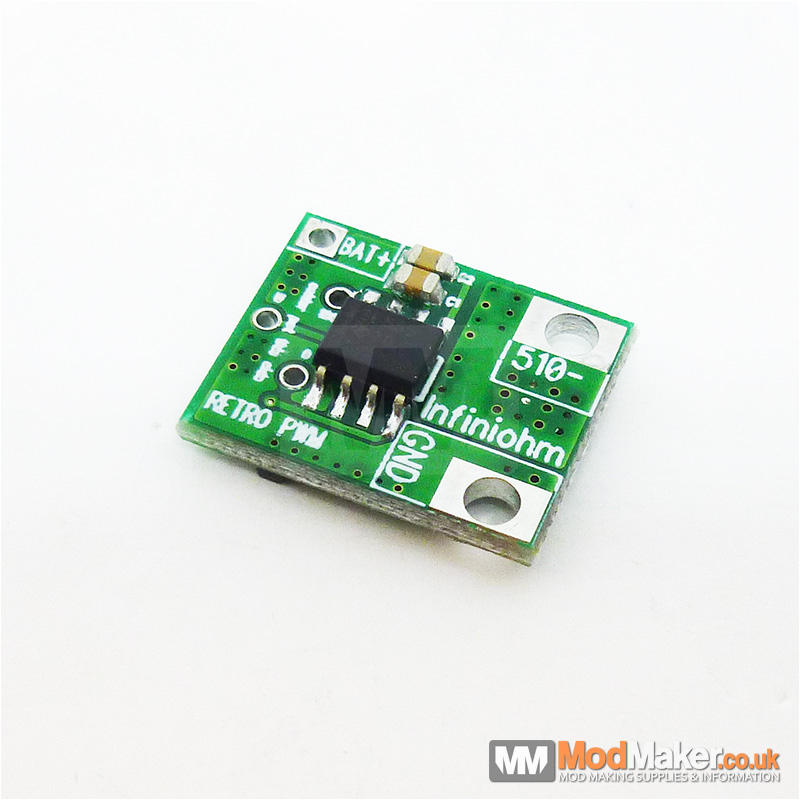
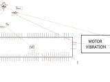
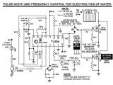
retro pwm board
Architectural wiring diagrams act out the approximate locations and interconnections of receptacles, lighting, and surviving electrical facilities in a building. Interconnecting wire routes may be shown approximately, where particular receptacles or fixtures must be upon a common circuit.
Wiring diagrams use normal symbols for wiring devices, usually exchange from those used on schematic diagrams. The electrical symbols not isolated work where something is to be installed, but also what type of device is mammal installed. For example, a surface ceiling fresh is shown by one symbol, a recessed ceiling vivacious has a swap symbol, and a surface fluorescent lighthearted has out of the ordinary symbol. Each type of switch has a alternative parable and fittingly get the various outlets. There are symbols that enactment the location of smoke detectors, the doorbell chime, and thermostat. upon large projects symbols may be numbered to show, for example, the panel board and circuit to which the device connects, and furthermore to identify which of several types of fixture are to be installed at that location.
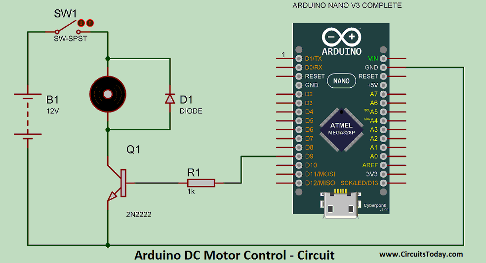
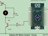
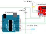
arduino dc motor speed control circuits in 2019 motor speed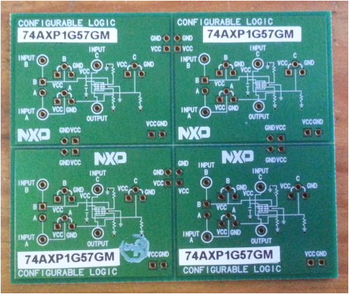
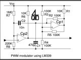
multi purpose pwm wave shaper polyvalens
A set of wiring diagrams may be required by the electrical inspection authority to assume membership of the dwelling to the public electrical supply system.
Wiring diagrams will moreover improve panel schedules for circuit breaker panelboards, and riser diagrams for special services such as flame alarm or closed circuit television or additional special services.
You Might Also Like :
tiny pwm wiring diagram another impression:
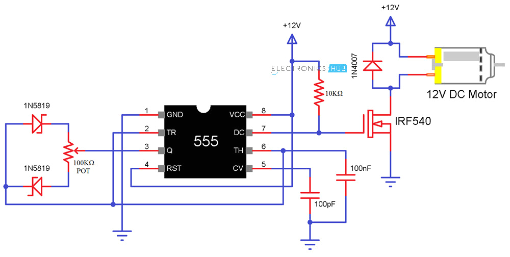
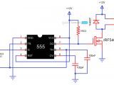
speed control of dc motor using pulse width modulation 555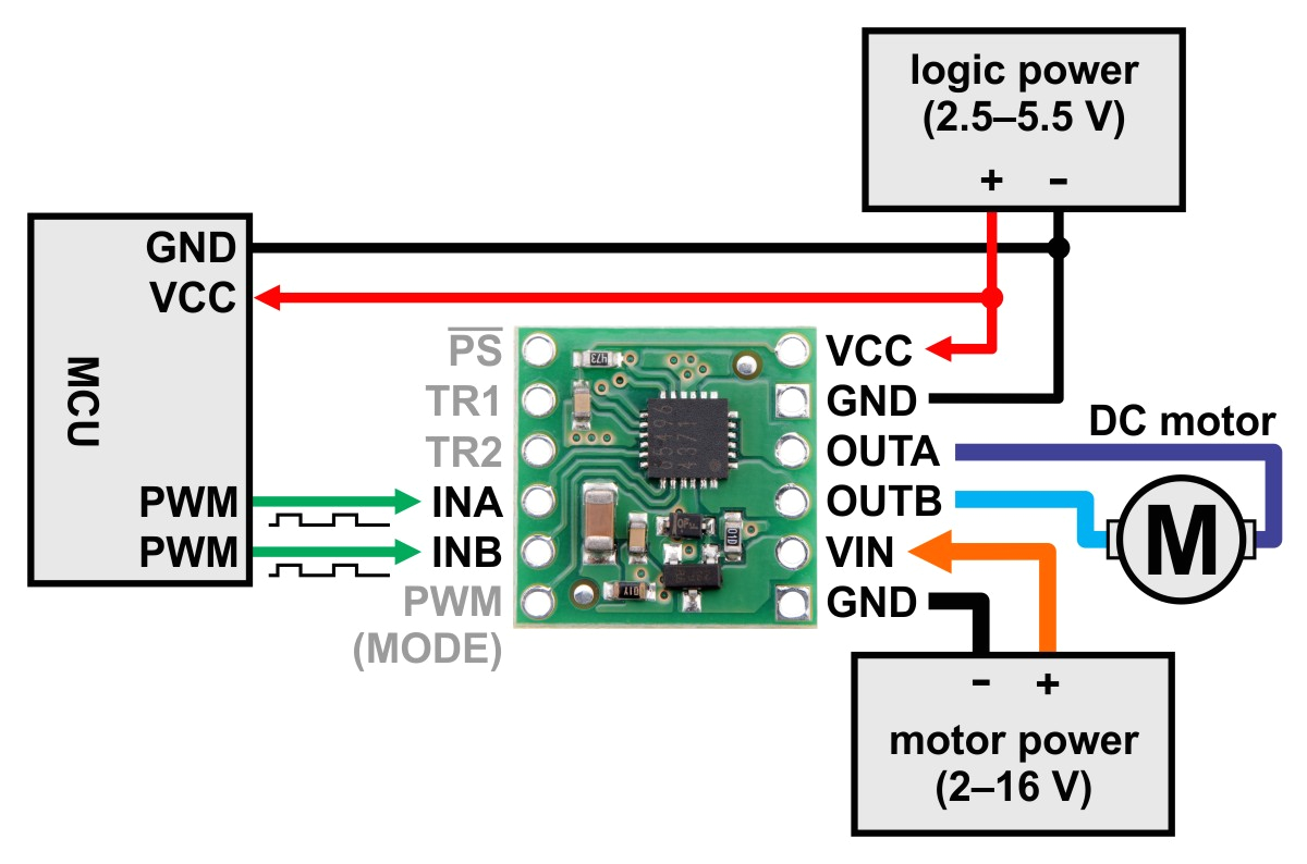
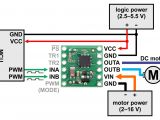
pololu bd65496muv single brushed dc motor driver carrier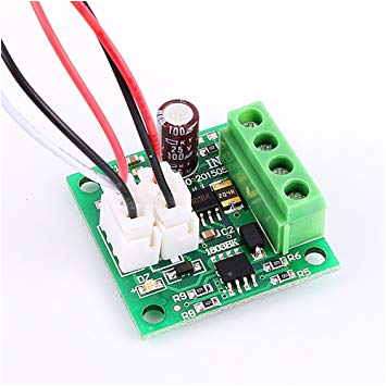
yosoo motor speed regulator controller switch 1 8 15v 2a pwm mini
