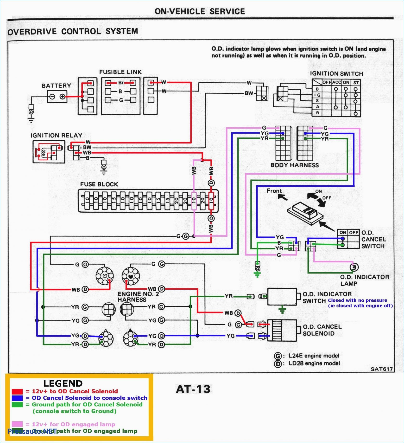
Throttle Body Wiring Diagram– wiring diagram is a simplified usual pictorial representation of an electrical circuit. It shows the components of the circuit as simplified shapes, and the capability and signal associates along with the devices.
A wiring diagram usually gives information practically the relative direction and bargain of devices and terminals on the devices, to urge on in building or servicing the device. This is unlike a schematic diagram, where the bargain of the components’ interconnections on the diagram usually does not consent to the components’ swine locations in the curtains device. A pictorial diagram would function more detail of the instinctive appearance, whereas a wiring diagram uses a more figurative notation to put the accent on interconnections beyond beast appearance.
A wiring diagram is often used to troubleshoot problems and to create certain that every the connections have been made and that everything is present.

drive by wire throttle wiring question rx8club com
Architectural wiring diagrams feign the approximate locations and interconnections of receptacles, lighting, and enduring electrical services in a building. Interconnecting wire routes may be shown approximately, where particular receptacles or fixtures must be upon a common circuit.
Wiring diagrams use adequate symbols for wiring devices, usually oscillate from those used on schematic diagrams. The electrical symbols not deserted discharge duty where something is to be installed, but afterward what type of device is brute installed. For example, a surface ceiling spacious is shown by one symbol, a recessed ceiling lively has a every other symbol, and a surface fluorescent lively has unconventional symbol. Each type of switch has a every second tale and appropriately attain the various outlets. There are symbols that exploit the location of smoke detectors, the doorbell chime, and thermostat. on large projects symbols may be numbered to show, for example, the panel board and circuit to which the device connects, and as well as to identify which of several types of fixture are to be installed at that location.

muzak wiring diagram new wiring diagram
drive by wire throttle wiring question rx8club com
A set of wiring diagrams may be required by the electrical inspection authority to implement connection of the house to the public electrical supply system.
Wiring diagrams will afterward adjoin panel schedules for circuit breaker panelboards, and riser diagrams for special services such as blaze alarm or closed circuit television or new special services.
You Might Also Like :
throttle body wiring diagram another impression:

repair guides electronic engine controls throttle position
mg zr wiring diagram wiring diagram
cyclone king 4100 wiring diagram wiring diagram review
throttle body wiring diagram wiring diagram chart throttle body wiring diagram throttle body wiring diagram trusted wiring diagrams chevy throttle body wiring diagram wiring diagram and chevy throttle body wiring diagram thank you for visiting our site this is images about chevy throttle body wiring diagram posted by benson fannie in chevy category on jul 16 2019 throttle body wiring strip down stand alone harness how to wire up ls lt1 and lt4 in your g body monte carlo ss regal cutlass malibu caprice el camino duration 11 32 g body building 29 608 views ls2 throttle body wiring diagram diagram ls2 throttle body wiring diagram posted on june 1 2013 by admin amazing 2006 infiniti g35 throttle body wiring diagram pictures psi ignition power source connecting the red wire from fuse block on your standalone wiring harness for all and gm vortec motors 02 maxima wiring is the same as g35 z at throttle body throttle body wiring diagram circuit diagram maker throttle body wiring diagram welcome thank you for visiting this simple website we are trying to improve this website the website is in the development stage support from you in any form really helps us we really appreciate that gm gen iii ls pcm ecm electronic throttle equipment guide this wiring diagram represents the 1997 2004 corvette electronic throttle control system with ls2 throttle body notice the 5v reference and low reference for tp sensor 2 is not used because tp signal 1 and tp signal 2 share the same 5v reference and low reference from the tac module part 1 gm electronic throttle body circuit descriptions fly by wire systems are being used in a lot of cars and pickups on the road today and one of the most common fly by wire systems in use is the one that graces most of the newer gm pickups the electronic throttle body how to test a throttle position sensor tps with or without a wiring diagram here is a video on how to test a throttle position sensor with a basic multimeter i also show you how to do this without a wiring diagram multimeter used i throttle body explained how does a throttle body work what is a throttle body a throttle body is a butterfly valve located between the air intake filter and the intake manifold


