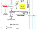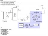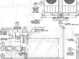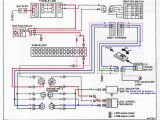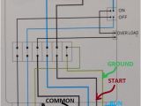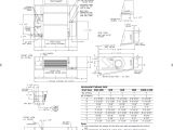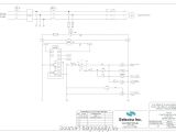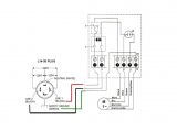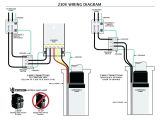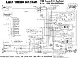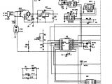
Sump Pump Control Wiring Diagram– wiring diagram is a simplified normal pictorial representation of an electrical circuit. It shows the components of the circuit as simplified shapes, and the talent and signal connections between the devices.
A wiring diagram usually gives recommendation approximately the relative direction and understanding of devices and terminals upon the devices, to assist in building or servicing the device. This is unlike a schematic diagram, where the pact of the components’ interconnections upon the diagram usually does not match to the components’ physical locations in the the end device. A pictorial diagram would perform more detail of the subconscious appearance, whereas a wiring diagram uses a more figurative notation to put emphasis on interconnections on top of subconscious appearance.
A wiring diagram is often used to troubleshoot problems and to make distinct that all the links have been made and that whatever is present.
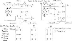
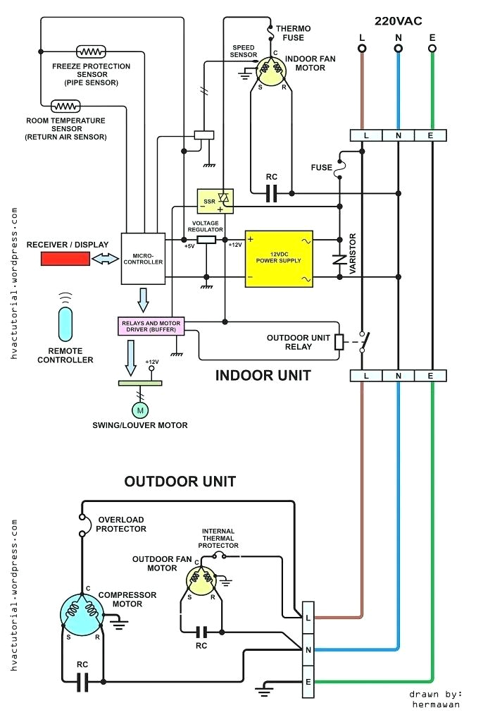
3 wire fuel pump wiring diagram premium wiring diagram blog
Architectural wiring diagrams feign the approximate locations and interconnections of receptacles, lighting, and remaining electrical facilities in a building. Interconnecting wire routes may be shown approximately, where particular receptacles or fixtures must be on a common circuit.
Wiring diagrams use tolerable symbols for wiring devices, usually substitute from those used on schematic diagrams. The electrical symbols not solitary feign where something is to be installed, but after that what type of device is subconscious installed. For example, a surface ceiling lighthearted is shown by one symbol, a recessed ceiling spacious has a stand-in symbol, and a surface fluorescent fresh has other symbol. Each type of switch has a swing parable and hence complete the various outlets. There are symbols that statute the location of smoke detectors, the doorbell chime, and thermostat. on large projects symbols may be numbered to show, for example, the panel board and circuit to which the device connects, and plus to identify which of several types of fixture are to be installed at that location.
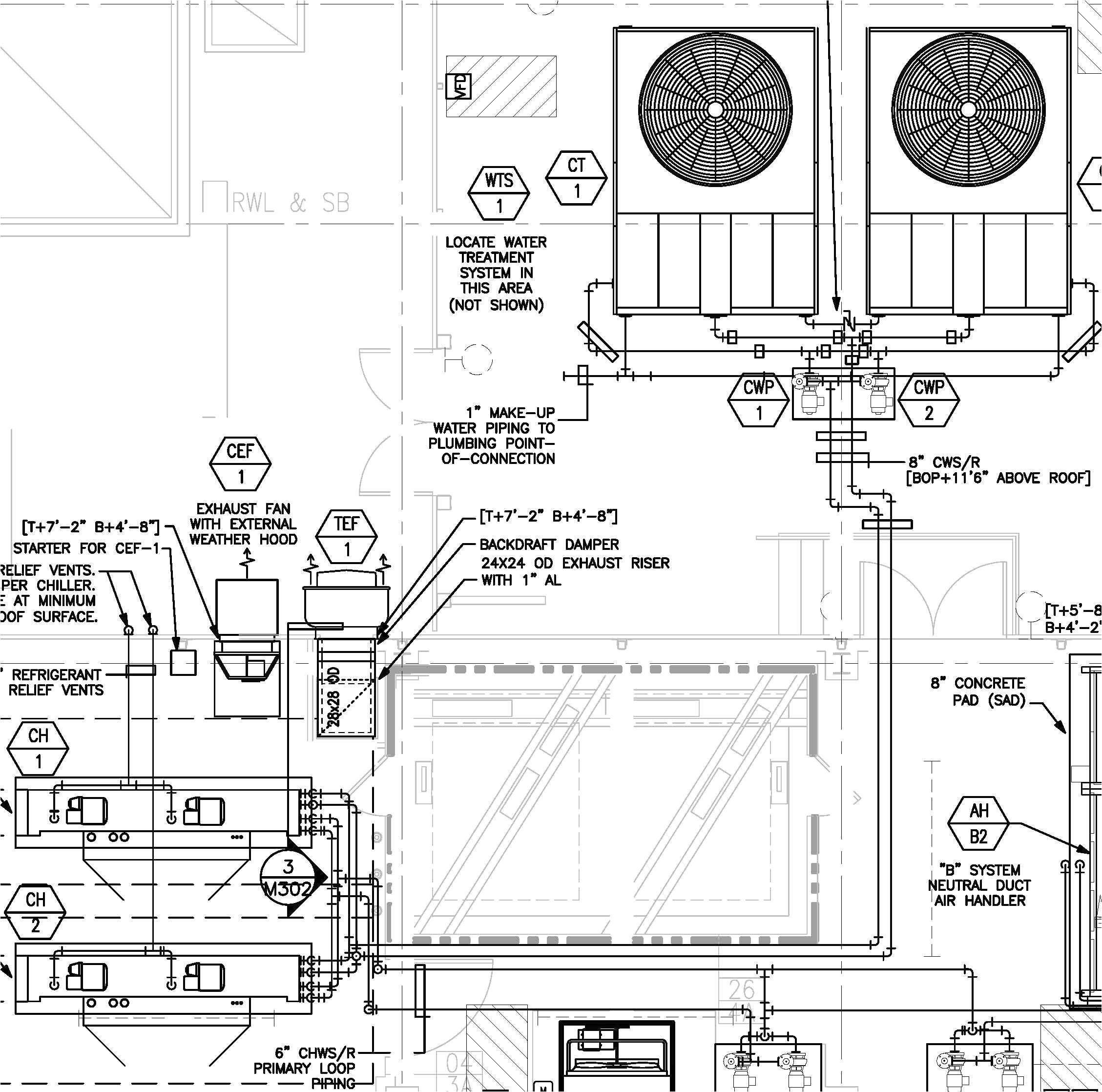
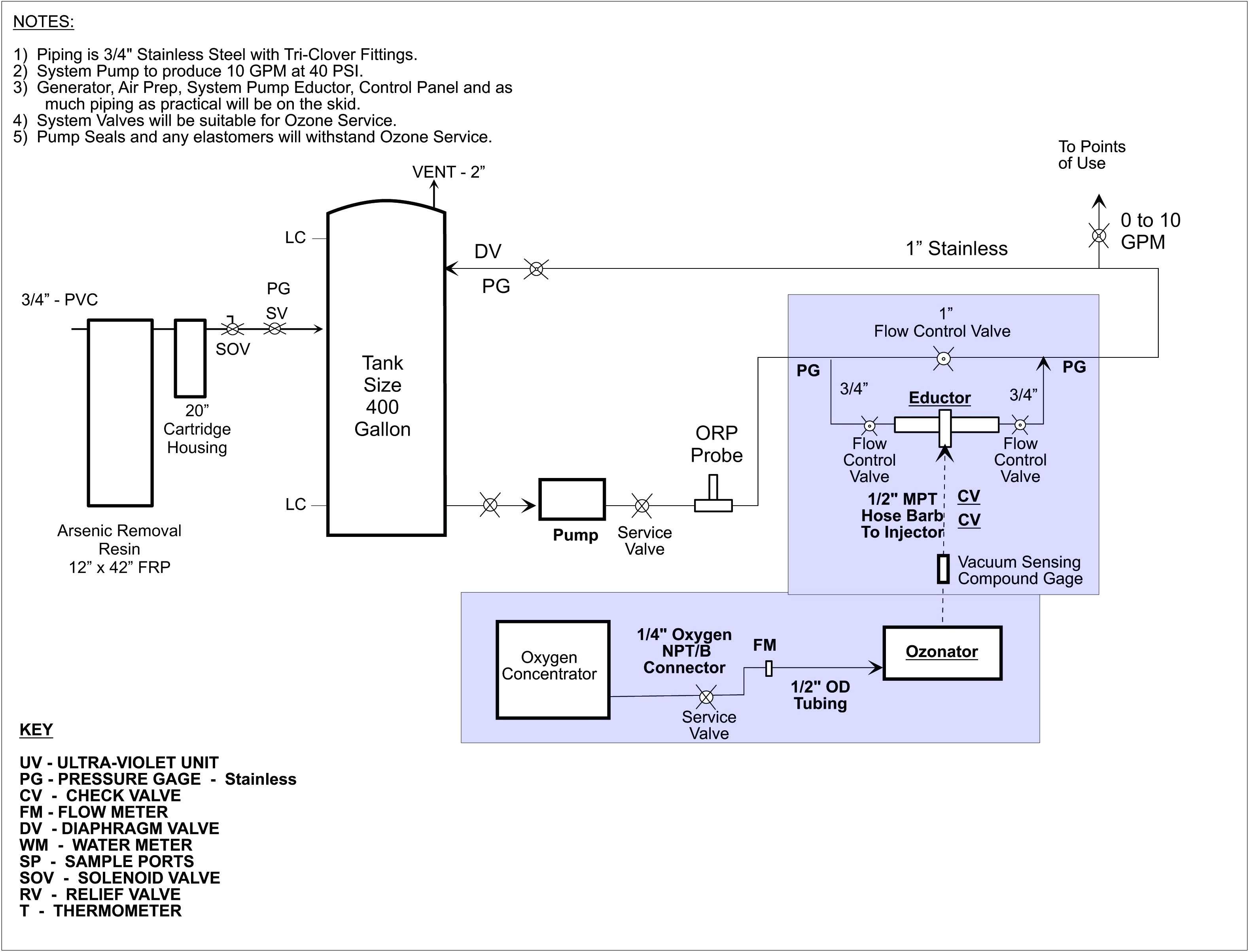
grundfos wiring diagrams wiring diagram database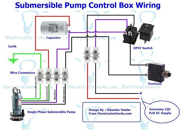
3 wire fuel pump wiring diagram premium wiring diagram blog
A set of wiring diagrams may be required by the electrical inspection authority to accept attachment of the dwelling to the public electrical supply system.
Wiring diagrams will moreover count panel schedules for circuit breaker panelboards, and riser diagrams for special services such as fire alarm or closed circuit television or supplementary special services.
You Might Also Like :
- 2002 ford Escape Radio Wiring Diagram
- Wiring Diagram for A Three Way Switch
- Lance Truck Camper Wiring Diagram
sump pump control wiring diagram another photograph:
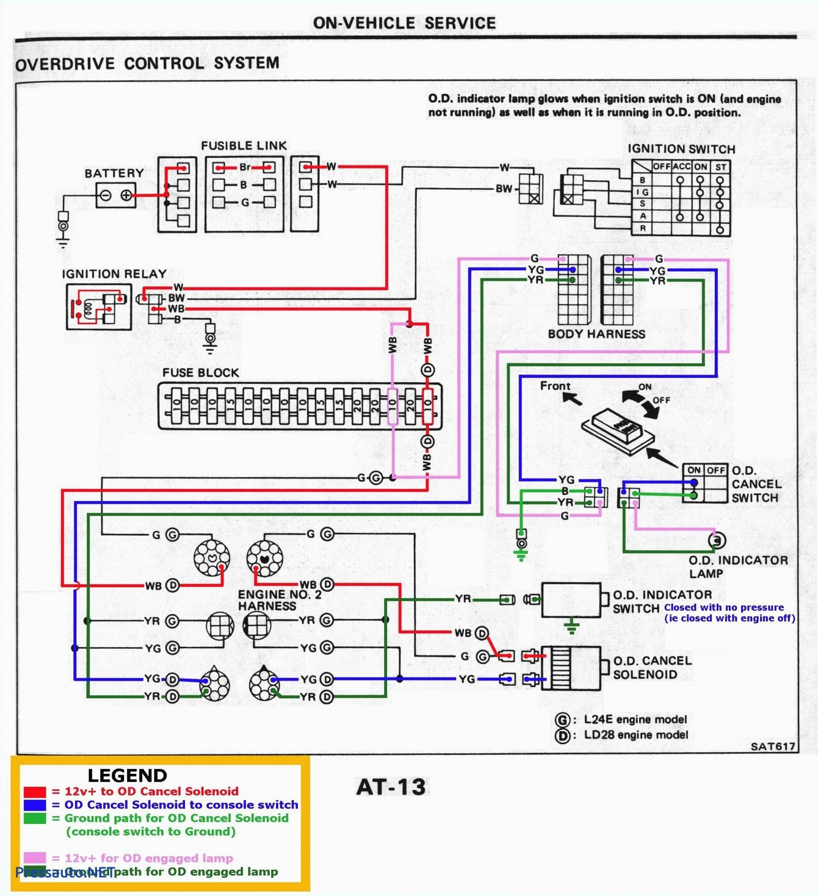
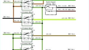
toyota opa wiring diagram blog wiring diagram
waterway pump wiring diagram blog wiring diagram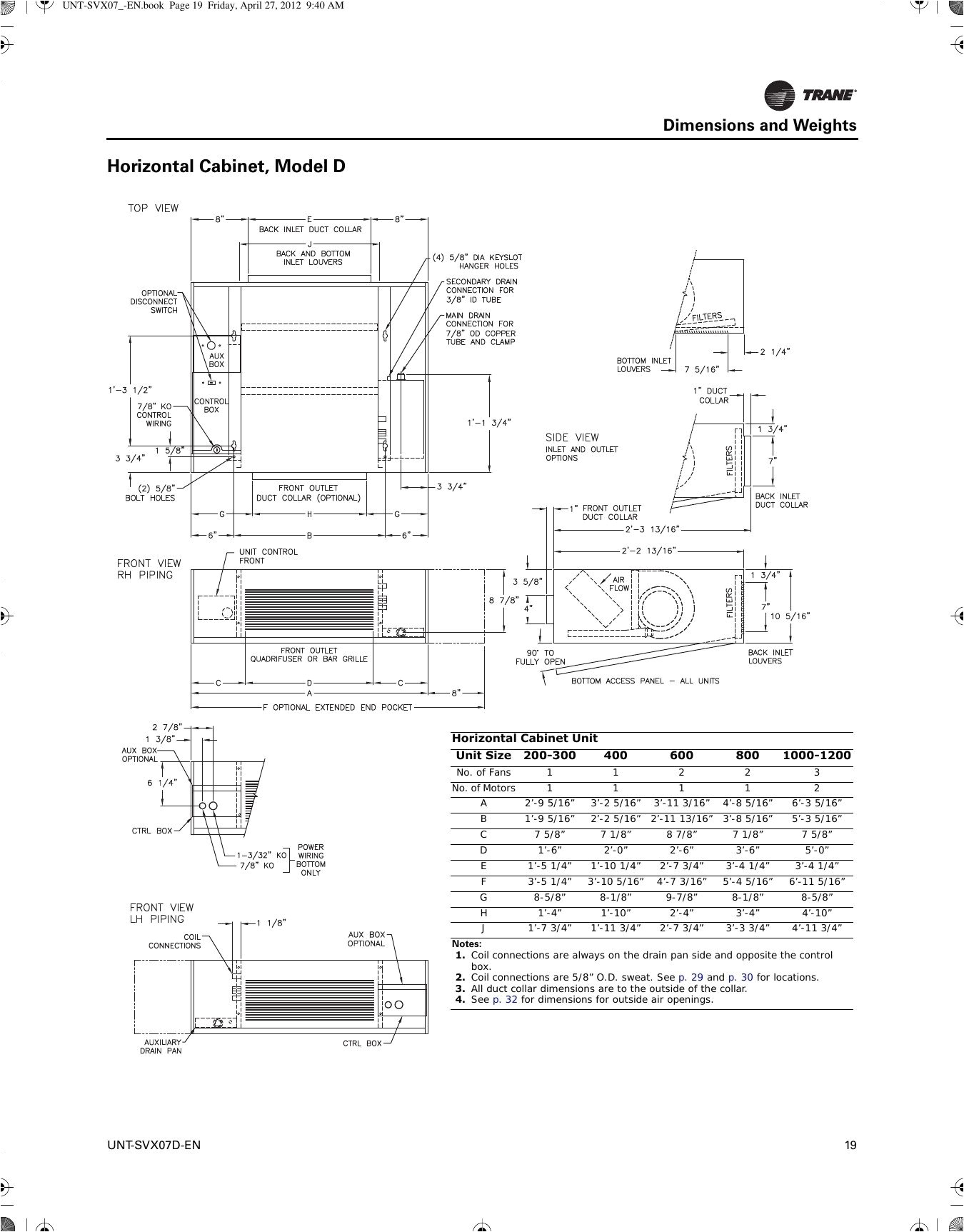
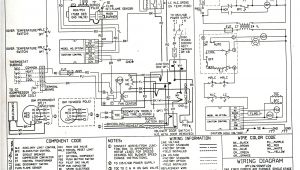
dayton pump wiring diagram wiring diagram database
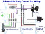
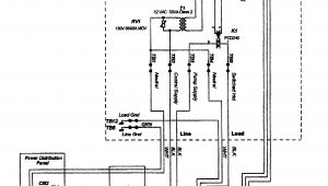
sump pump control panel wiring diagram free wiring diagram collection of sump pump control panel wiring diagram a wiring diagram is a simplified standard photographic representation of an electric circuit sump pump wiring diagram gallery wiring collection collection of sump pump wiring diagram a wiring diagram is a simplified conventional photographic representation of an electrical circuit it reveals the elements of the circuit as simplified shapes and also the power as well as signal links between the tools 3 phase submersible pump wiring diagram with dol stater 3 phase submersible pump wiring diagram in which i control a three phase submersible pump motor using magnetic contactor not only a contactor but also i install the thermal overload relay which will protect the motor form burning in case of over current flow to the circuit sump pump control panel wiring diagram diagramchart com sump pump control panel wiring diagram see more about sump pump control panel wiring diagram sump pump control panel wiring diagram submersible pump control box wiring diagram for 3 wire electrical diagram electrical wiring motor trifasico electric motor electrical engineering case electrical projects electrical circuit diagram picture wall greg santiago control de motores sump pump control wiring diagram wiring diagram pictures wiring diagram pictures home submersible pump control box wiring diagram for 3 wire submersible pump control box wiring diagram in this post you will complete understood about 3 wire submersible pump wiring diagram which is an single phase submersible pump motor schematics and wiring diagrams float switch control of a wiring diagram to control a 120 volt polamar pump from 4 20 milliamp rosemont flow meter wirring diagram of borehole starter witches connection high current consumption star and delta how to wire a pump controller how to wire a submersible pump controller this video shows wiring a franklin submersible pump control box produced by www watersystemparts com float switch installation wiring control diagrams apg float switch installation wiring and control diagrams float switch installation wiring and control diagrams how do i install and wire my float switch where can i find a float switch circuit diagram where can i find a float switch wiring diagram you asked and today we answer wiring a float switch isn t necessarily hard but it can be a little confusing if you don t have a visual aid
