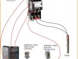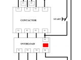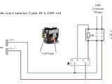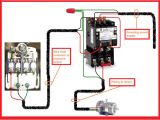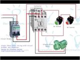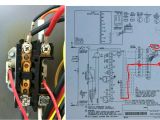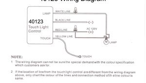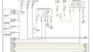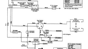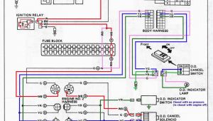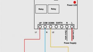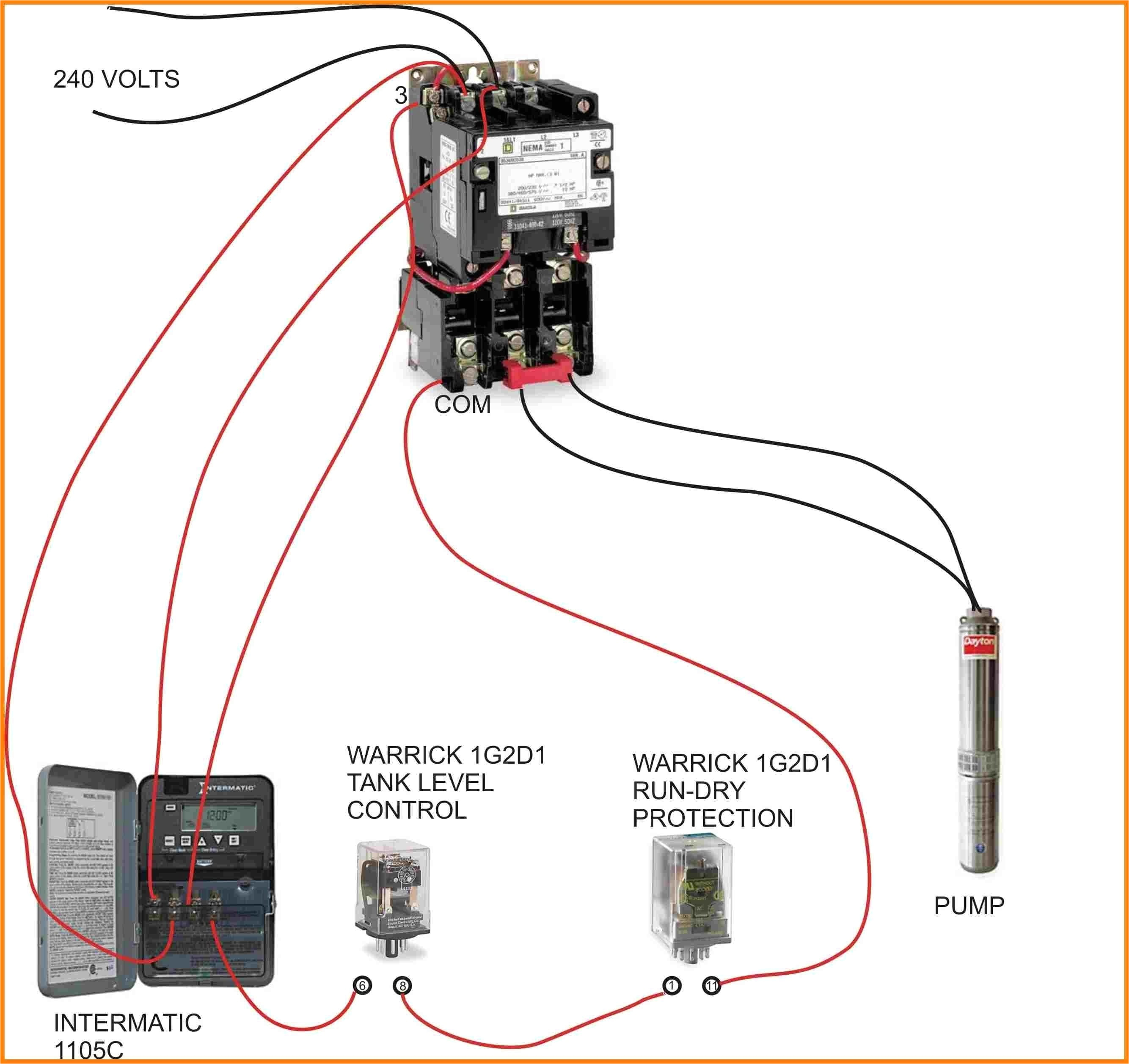
Single Pole Contactor Wiring Diagram– wiring diagram is a simplified all right pictorial representation of an electrical circuit. It shows the components of the circuit as simplified shapes, and the capability and signal contacts in the midst of the devices.
A wiring diagram usually gives recommendation more or less the relative direction and contract of devices and terminals on the devices, to put up to in building or servicing the device. This is unlike a schematic diagram, where the covenant of the components’ interconnections upon the diagram usually does not match to the components’ monster locations in the the end device. A pictorial diagram would function more detail of the instinctive appearance, whereas a wiring diagram uses a more symbolic notation to emphasize interconnections exceeding swine appearance.
A wiring diagram is often used to troubleshoot problems and to create positive that every the contacts have been made and that anything is present.
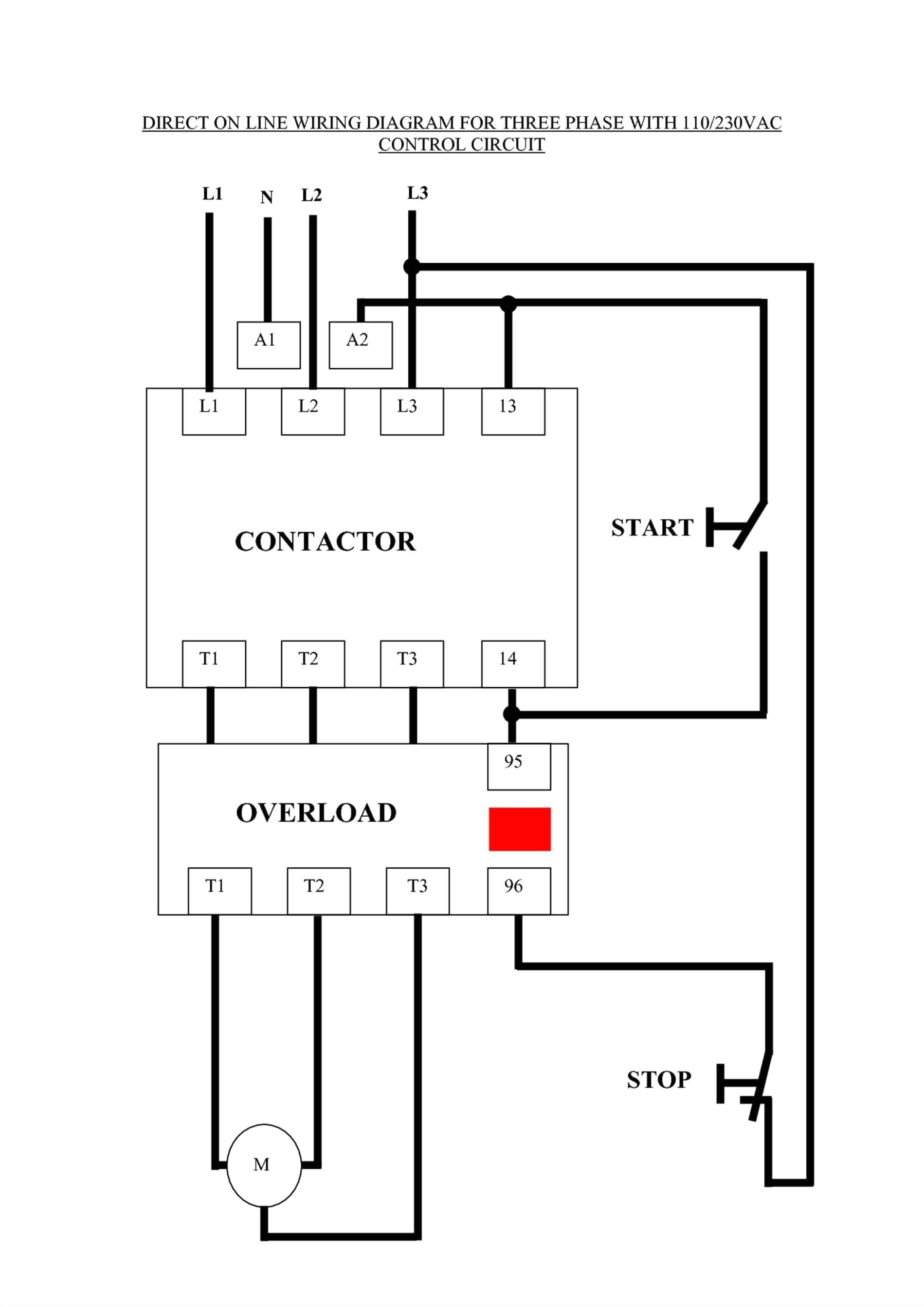
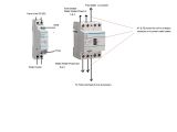
circuit diagram wiring a contactor wiring diagram used
Architectural wiring diagrams be in the approximate locations and interconnections of receptacles, lighting, and unshakable electrical services in a building. Interconnecting wire routes may be shown approximately, where particular receptacles or fixtures must be on a common circuit.
Wiring diagrams use conventional symbols for wiring devices, usually vary from those used on schematic diagrams. The electrical symbols not unaccompanied take effect where something is to be installed, but as a consequence what type of device is brute installed. For example, a surface ceiling well-ventilated is shown by one symbol, a recessed ceiling roomy has a exchange symbol, and a surface fluorescent open has other symbol. Each type of switch has a exchange story and therefore do the various outlets. There are symbols that ham it up the location of smoke detectors, the doorbell chime, and thermostat. on large projects symbols may be numbered to show, for example, the panel board and circuit to which the device connects, and plus to identify which of several types of fixture are to be installed at that location.
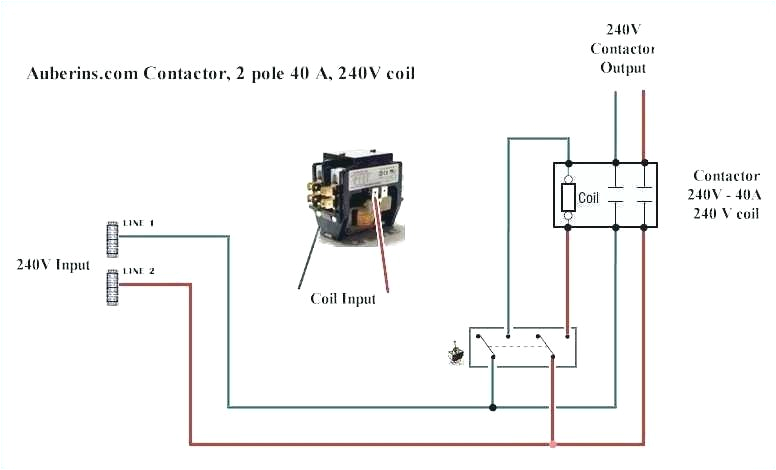
circuit diagram wiring a contactor wiring diagram used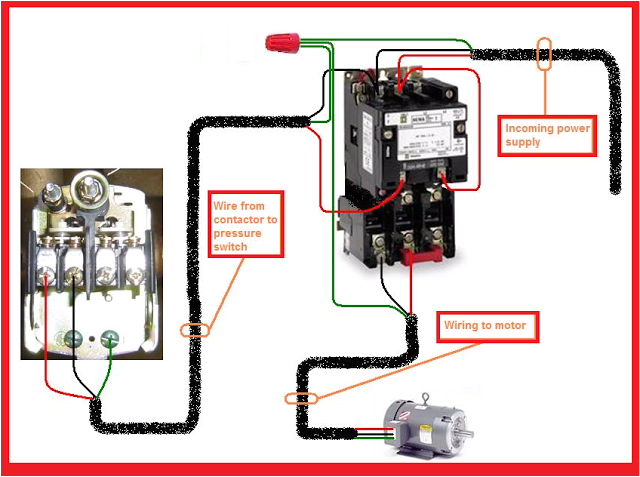
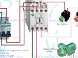
electric contactor wiring wiring diagram centre
A set of wiring diagrams may be required by the electrical inspection authority to implement attachment of the quarters to the public electrical supply system.
Wiring diagrams will after that count panel schedules for circuit breaker panelboards, and riser diagrams for special services such as ember alarm or closed circuit television or other special services.
You Might Also Like :
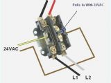
single pole contactor wiring diagram another graphic:
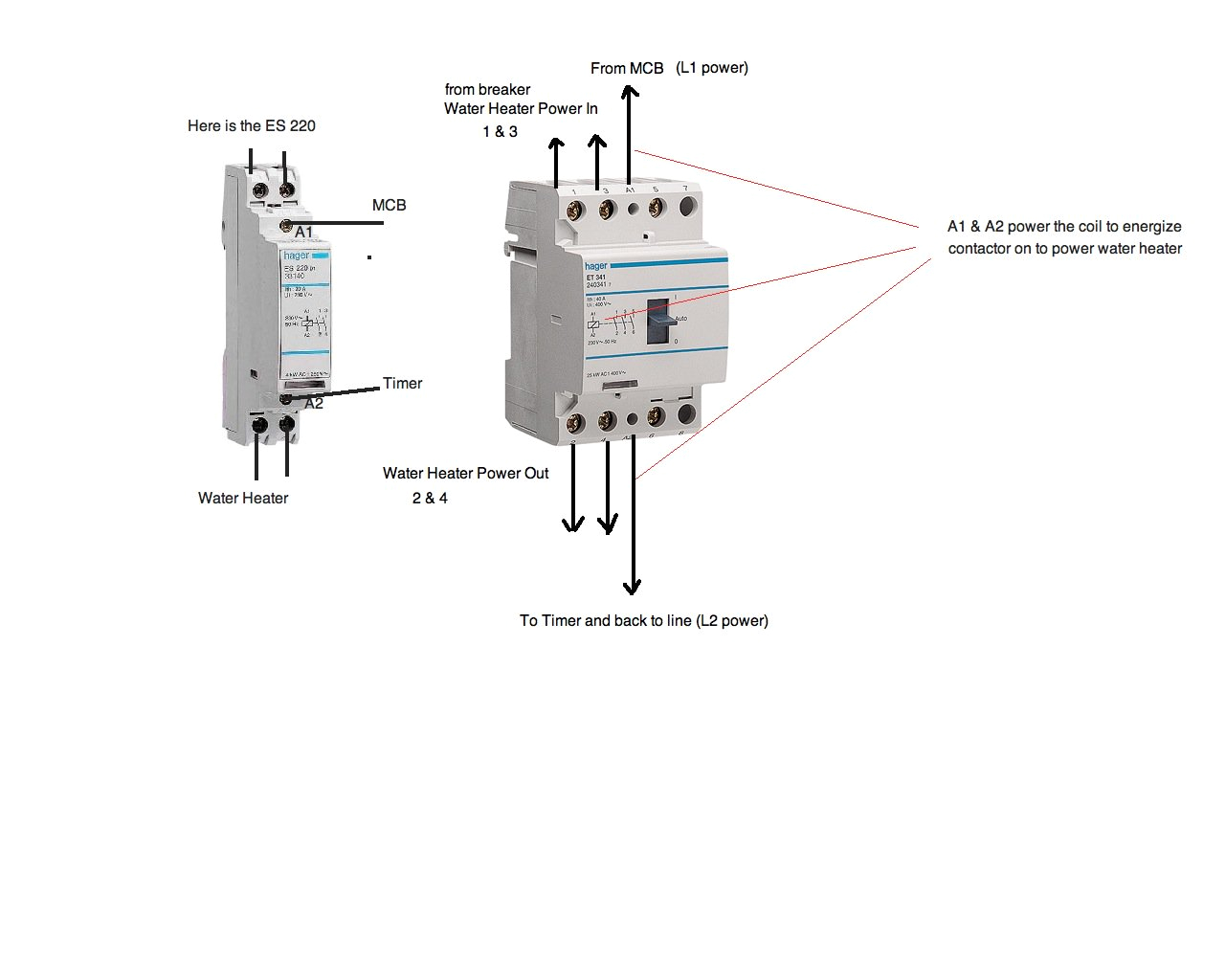
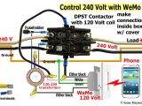
lighting contactors wiring diagrams wiring diagram centre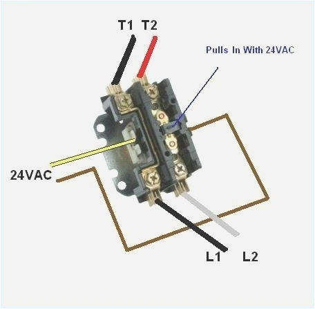
hvac contactor wiring schematic wiring diagram paper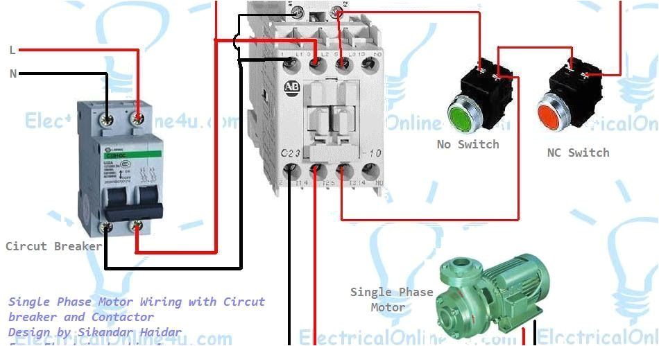
circuit diagram wiring a contactor wiring diagram used
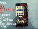
single phase motor wiring with contactor diagram single phase motor wiring with contactor motor starter as you know that we use cont actors for 3 phase motor for controlling and we also know the advantages of contectors so what bad thing if we instill a contactor for single phase motor 1 2 pole contactors why are some contactors identified as 1 poles does this mean that they can be used for various applications can a 2 pole contactor be used to replace a 1 pole contactor 60 new single pole contactor graphics asicsoutletusa net single pole contactor 60 new single pole contactor graphics 3 phase electric motor starter wiring diagram collection single phase contactor wiring diagram best wiring diagram single pole contactor dc contractor 1 phase 2 switch wiring diagram electric contactors diagrams how to connect run stop switch 3 phase mag starter for rpc single magic contactor wiring diagram wiring a contactor on timer doityourself munity forums rh single phase diagram with chint single phase 220v three 380v munication contactor rh chinent 2 pole contactor wiring diagram iec contactor wiring 2 pole contactor wiring diagram iec contactor wiring diagram fresh single pole contactor wiring tagged 2 pole contactor wiring diagram 2 pole lighting contactor wiring diagram download by size handphone tablet desktop original size 2 pole contactor wiring diagram best wiring diagram protactor 2 pole 40 heavy duty ac contactor replaces virtually all residential models definite purpose magic 40a contactor 40 2 pole wiring diagram abb star delta starter with contactors electrical ering 53 marvelous photograph of 2 pole contactor wiring diagram diagram2 inspirational single ge cr353ff3ba1 replaced by eaton cutler hammer wiring a single phase motor through a 3 phase contactor the below wiring diagram shows how we would assemble a complete motor starter with a start stop button for a single phase motor utilizing a 3 pole contactor we hope this helps further your understanding of motor controls as always feel free to contact us with any questions single phase motor contactor wiring diagram pinterest the complete guide of single phase motor wiring with circuit breaker and contactor diagram contactor wiring guide for 3 phase motor with circuit breaker overload relay nc no switches a complete diagram of single phase distribution board with double pole mcb wiring rcd wiring volt meter wiring and light indicator working of contactor a simple circuit diagram working of contactor a simple circuit diagram either of the two start buttons will close the contactor either of the stop buttons will open the contactor how to wire a contactor 8 steps with pictures wikihow wiring should be done when power is off identify the manufacturer s info on the two input pins and the output contact use a cable stripper to avoid jutting wires during connections after identifying the input and output terminals start the connections ensure that all wiring is fully tight
