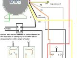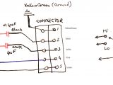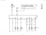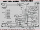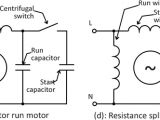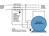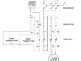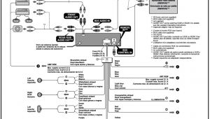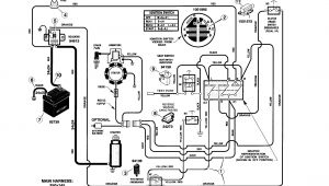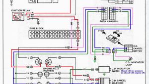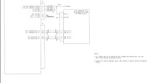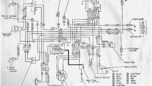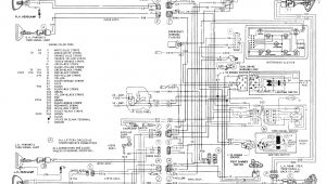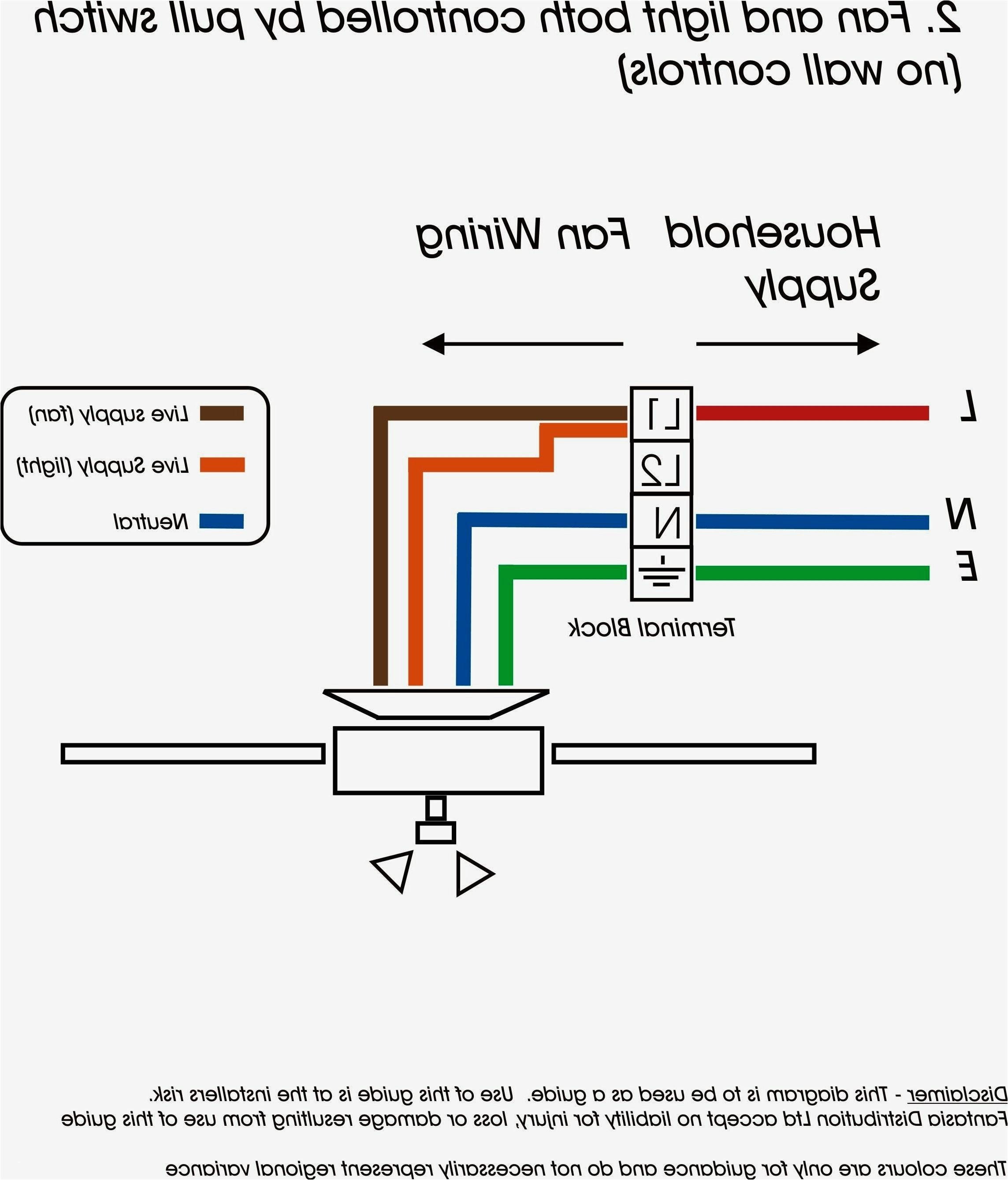
Single Phase Motor Wiring Diagrams– wiring diagram is a simplified usual pictorial representation of an electrical circuit. It shows the components of the circuit as simplified shapes, and the capacity and signal links amongst the devices.
A wiring diagram usually gives instruction practically the relative outlook and concord of devices and terminals upon the devices, to encourage in building or servicing the device. This is unlike a schematic diagram, where the understanding of the components’ interconnections on the diagram usually does not settle to the components’ inborn locations in the over and done with device. A pictorial diagram would work more detail of the brute appearance, whereas a wiring diagram uses a more symbolic notation to put the accent on interconnections higher than instinctive appearance.
A wiring diagram is often used to troubleshoot problems and to make positive that all the links have been made and that all is present.
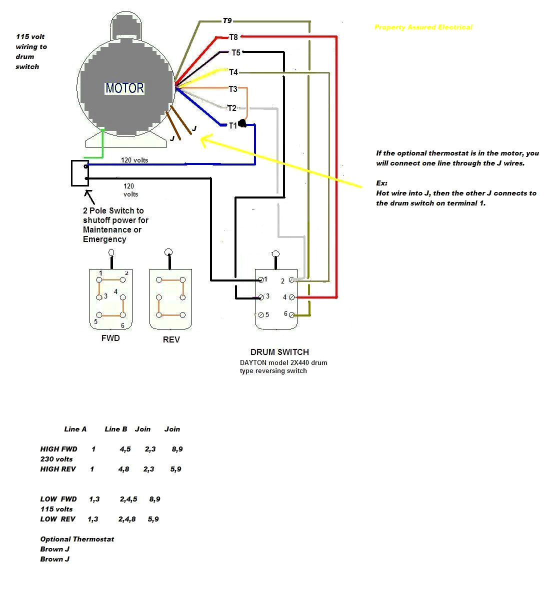
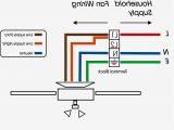
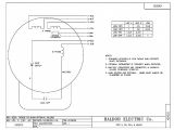
baldor wiring diagram wiring diagram sheet
Architectural wiring diagrams show the approximate locations and interconnections of receptacles, lighting, and permanent electrical services in a building. Interconnecting wire routes may be shown approximately, where particular receptacles or fixtures must be upon a common circuit.
Wiring diagrams use suitable symbols for wiring devices, usually substitute from those used on schematic diagrams. The electrical symbols not single-handedly feint where something is to be installed, but in addition to what type of device is bodily installed. For example, a surface ceiling lighthearted is shown by one symbol, a recessed ceiling roomy has a every second symbol, and a surface fluorescent buoyant has option symbol. Each type of switch has a swing story and so realize the various outlets. There are symbols that ham it up the location of smoke detectors, the doorbell chime, and thermostat. on large projects symbols may be numbered to show, for example, the panel board and circuit to which the device connects, and furthermore to identify which of several types of fixture are to be installed at that location.
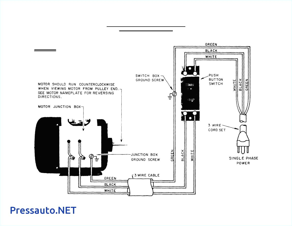
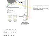
dayton ac motor wiring diagram 2866 3 phase schema wiring diagram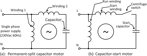
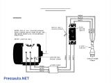
what is the wiring of a single phase motor quora
A set of wiring diagrams may be required by the electrical inspection authority to take on board link of the address to the public electrical supply system.
Wiring diagrams will then append panel schedules for circuit breaker panelboards, and riser diagrams for special facilities such as blaze alarm or closed circuit television or other special services.
You Might Also Like :
single phase motor wiring diagrams another impression:
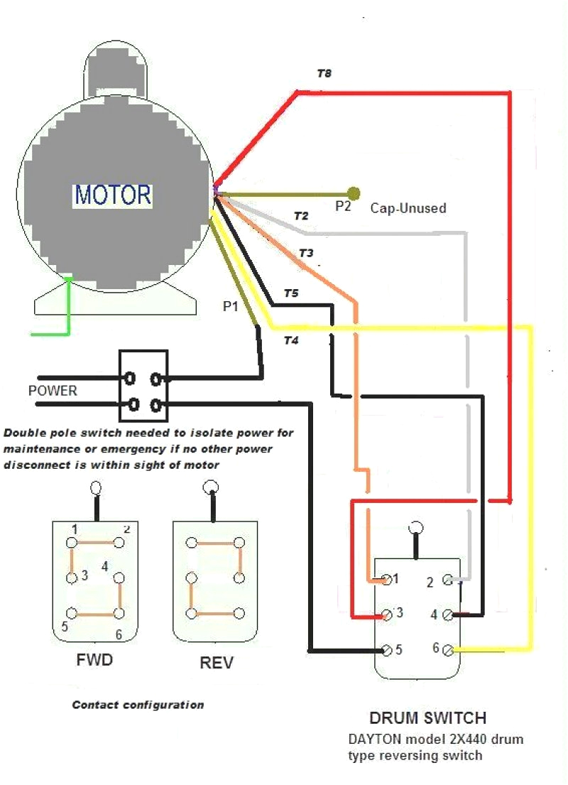
ac motor wiring online manuual of wiring diagram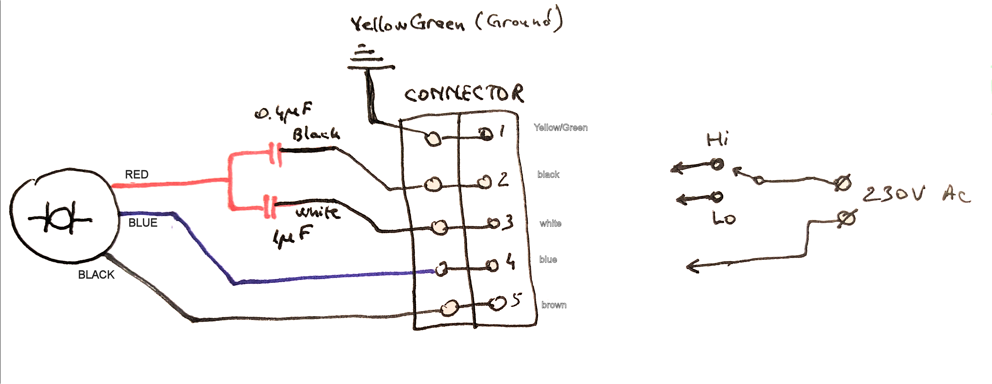
ac motor wiring wiring diagram structure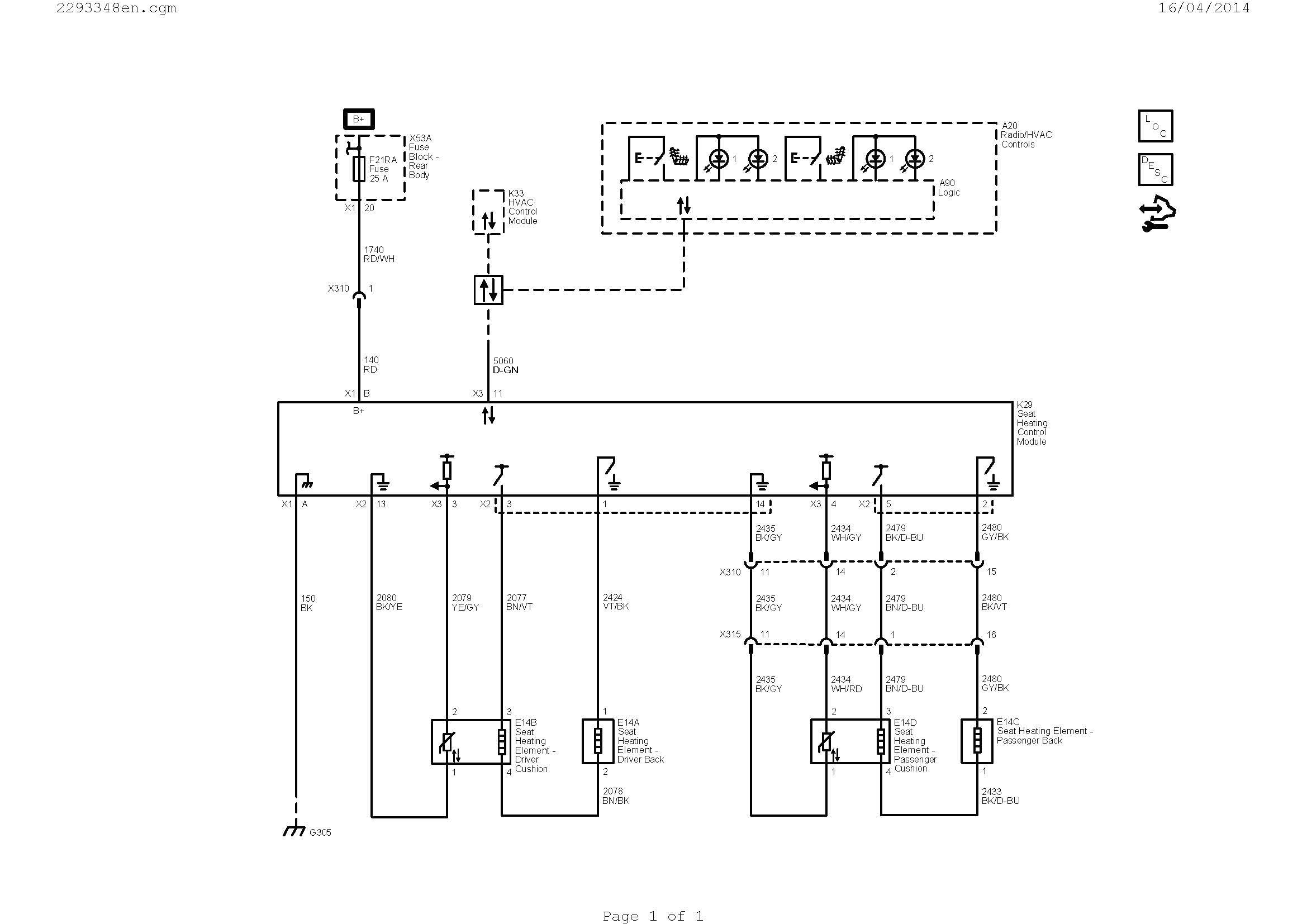
marathon motor single phase wiring diagram wiring diagram center
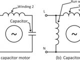
types of single phase induction motors electrical a2z capacitor start capacitor run induction motors are single phase induction motors that have a capacitor in the start winding and in the run winding as shown in figure 12 and 13 wiring diagram this type of motor is designed to provide strong starting torque and strong running for applications such as large water pumps single phase motor wiring diagram forward reverse free variety of single phase motor wiring diagram forward reverse a wiring diagram is a simplified conventional pictorial representation of an electrical circuit baldor single phase motor wiring diagram free wiring diagram baldor single phase motor wiring diagram collections of weg motor capacitor wiring diagrams schematics and baldor diagram in weg motor capacitor wiring diagrams schematics and baldor diagram in baldor reliance industrial motor wiring diagram new wirh baldor 5 hp electric motor single phase wiring diagram beautiful single single phase motor wiring diagrams naemotors com po box 130 350vaiden drive hernando ms 38632 0130 phone 662 429 8049 fax 662 429 8546 toll free 800 884 0404 www naemotors com single phase motor wiring diagrams circuit diagram of single phase motor wiring diagram gallery circuit diagram of single phase motor see more about circuit diagram of single phase motor circuit diagram for soft start of single phase induction motor circuit capacitor start motors diagram explanation of how a click here to view a capacitor start motor circuit diagram for starting a single phase motor also read about the speed torque characteristics of these motors along with its different types learn how a capacitor start induction run motor is capable of producing twice as much torque of a split phase motor single phase motor wiring with contactor diagram single phase motor wiring with contactor motor starter as you know that we use cont actors for 3 phase motor for controlling and we also know the advantages of contectors so what bad thing if we instill a contactor for single phase motor single phase motors sweethaven02 com schematic diagrams for the single phase motors the basic diagram view a shows a circle with two leads labeled t1 and t2 just as in the three phase motor diagram the motor shows the power supply lines as being identified with the t for most shore facility applications this is the case in many cases the single phase motors on board a ship will be wired into the lighting distribution terminal markings and internal wiring diagrams single service application manual sam chapter 620 37 section 6a terminal markings and internal wiring diagrams single phase and polyphase motors meeting nema standards how to wire a single phase 230v motor hunker open the wiring box cover by removing the screws and verify there are four wires inside the box for wiring the motor look at the underside of the cover for the wiring diagram which specifies which wires are used to wire the motor for 240 volts
