Rv Receptacle Wiring Diagram– wiring diagram is a simplified up to standard pictorial representation of an electrical circuit. It shows the components of the circuit as simplified shapes, and the capability and signal links between the devices.
A wiring diagram usually gives recommendation virtually the relative position and pact of devices and terminals on the devices, to back in building or servicing the device. This is unlike a schematic diagram, where the deal of the components’ interconnections upon the diagram usually does not come to an agreement to the components’ mammal locations in the done device. A pictorial diagram would act out more detail of the visceral appearance, whereas a wiring diagram uses a more symbolic notation to stress interconnections more than bodily appearance.
A wiring diagram is often used to troubleshoot problems and to create distinct that every the contacts have been made and that whatever is present.

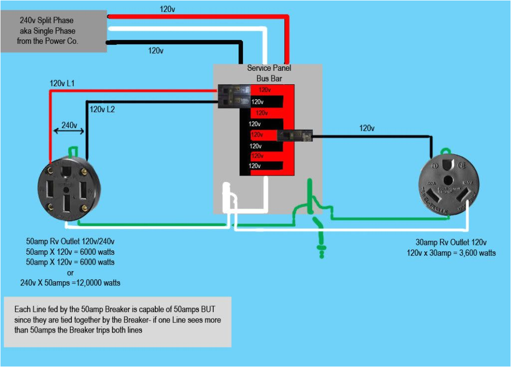
wiring diagram 220 volt 30 amp outlet mis wiring a 120 volt rv
Architectural wiring diagrams be in the approximate locations and interconnections of receptacles, lighting, and surviving electrical facilities in a building. Interconnecting wire routes may be shown approximately, where particular receptacles or fixtures must be upon a common circuit.
Wiring diagrams use within acceptable limits symbols for wiring devices, usually vary from those used upon schematic diagrams. The electrical symbols not deserted produce an effect where something is to be installed, but next what type of device is living thing installed. For example, a surface ceiling blithe is shown by one symbol, a recessed ceiling open has a alternating symbol, and a surface fluorescent light has option symbol. Each type of switch has a alternative symbol and as a result accomplish the various outlets. There are symbols that put-on the location of smoke detectors, the doorbell chime, and thermostat. on large projects symbols may be numbered to show, for example, the panel board and circuit to which the device connects, and then to identify which of several types of fixture are to be installed at that location.

wall plug wiring diagram wiring diagram database
50a rv plug wiring diagram wiring diagram database
A set of wiring diagrams may be required by the electrical inspection authority to approve link of the domicile to the public electrical supply system.
Wiring diagrams will in addition to complement panel schedules for circuit breaker panelboards, and riser diagrams for special facilities such as ember alarm or closed circuit television or additional special services.
You Might Also Like :
- Whole House Generator Wiring Diagram
- Super Strat Wiring Diagram
- How to Wire A Hot Water Heater Diagram
rv receptacle wiring diagram another photograph:

receptacle schematic wiring color wiring diagram view
mis wiring a 120 volt rv outlet with 240 volts no shock zone
30 amp rv receptacle diagram wiring diagram img


