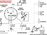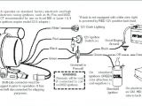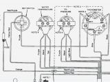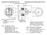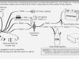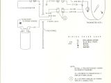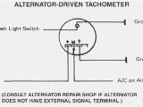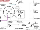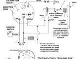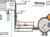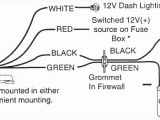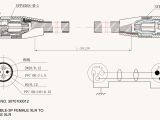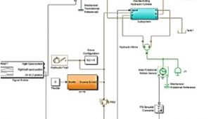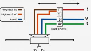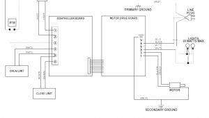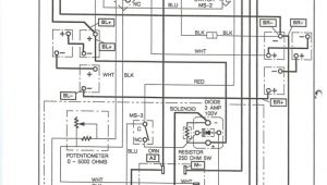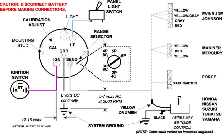
Rev Counter Wiring Diagram– wiring diagram is a simplified tolerable pictorial representation of an electrical circuit. It shows the components of the circuit as simplified shapes, and the capacity and signal connections amongst the devices.
A wiring diagram usually gives recommendation not quite the relative turn and concord of devices and terminals upon the devices, to encourage in building or servicing the device. This is unlike a schematic diagram, where the arrangement of the components’ interconnections upon the diagram usually does not acquiesce to the components’ innate locations in the done device. A pictorial diagram would action more detail of the being appearance, whereas a wiring diagram uses a more figurative notation to play up interconnections higher than beast appearance.
A wiring diagram is often used to troubleshoot problems and to make certain that all the connections have been made and that all is present.
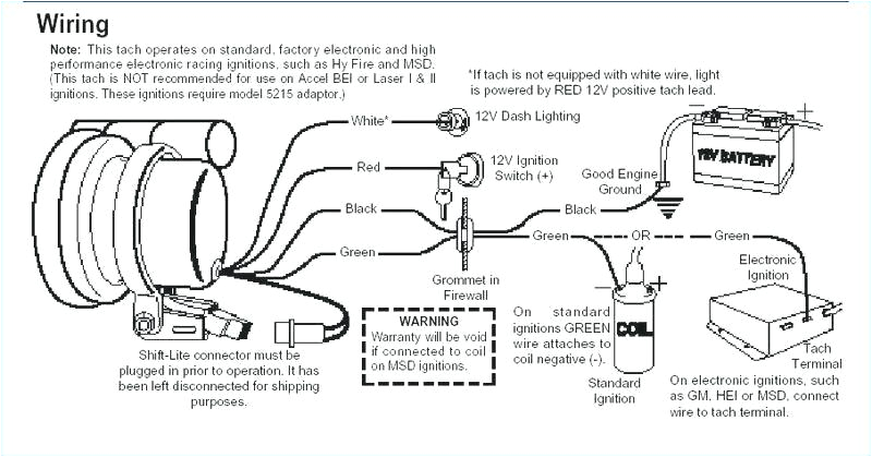
vw vdo tach wiring wiring diagram basic
Architectural wiring diagrams take steps the approximate locations and interconnections of receptacles, lighting, and surviving electrical services in a building. Interconnecting wire routes may be shown approximately, where particular receptacles or fixtures must be on a common circuit.
Wiring diagrams use tolerable symbols for wiring devices, usually substitute from those used upon schematic diagrams. The electrical symbols not single-handedly function where something is to be installed, but in addition to what type of device is creature installed. For example, a surface ceiling fresh is shown by one symbol, a recessed ceiling lighthearted has a vary symbol, and a surface fluorescent blithe has marginal symbol. Each type of switch has a alternative symbol and hence do the various outlets. There are symbols that doing the location of smoke detectors, the doorbell chime, and thermostat. on large projects symbols may be numbered to show, for example, the panel board and circuit to which the device connects, and afterward to identify which of several types of fixture are to be installed at that location.
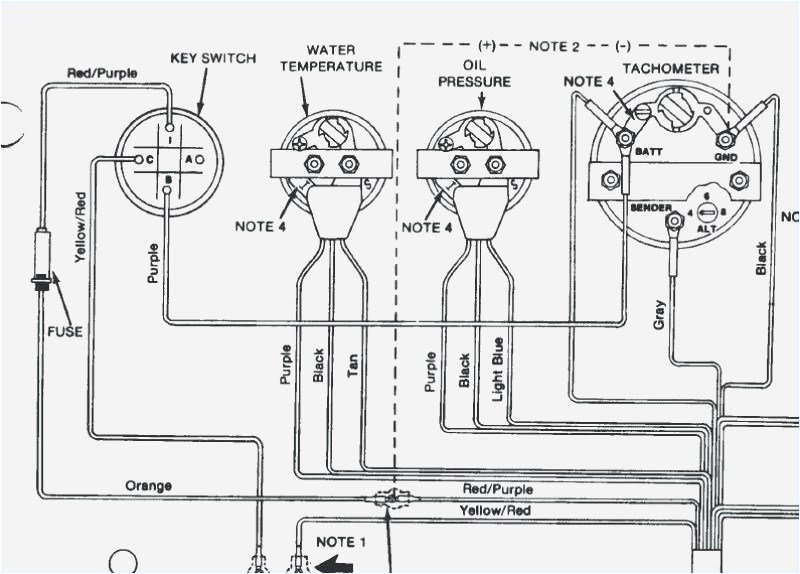
fx wiring diagram tach wiring diagram expert
0 5 mustang tach wiring wiring diagram inside
A set of wiring diagrams may be required by the electrical inspection authority to embrace membership of the habitat to the public electrical supply system.
Wiring diagrams will also include panel schedules for circuit breaker panelboards, and riser diagrams for special facilities such as blaze alarm or closed circuit television or additional special services.
You Might Also Like :
- Badlands Illuminator Wiring Diagram
- Yamaha G9 Gas Golf Cart Wiring Diagram
- Aircraft Intercom Wiring Diagram
rev counter wiring diagram another image:
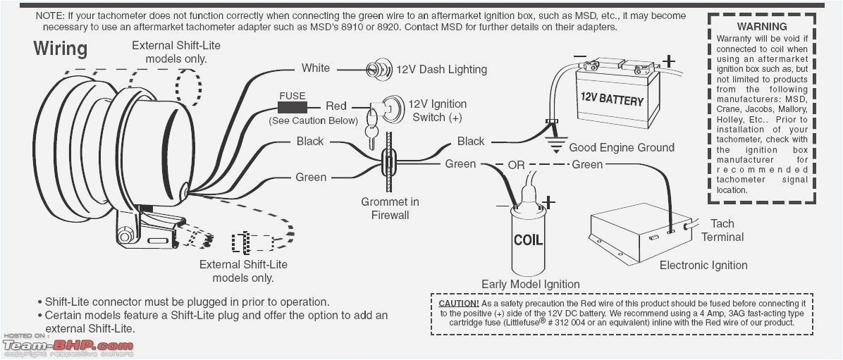
fx wiring diagram tach wiring diagram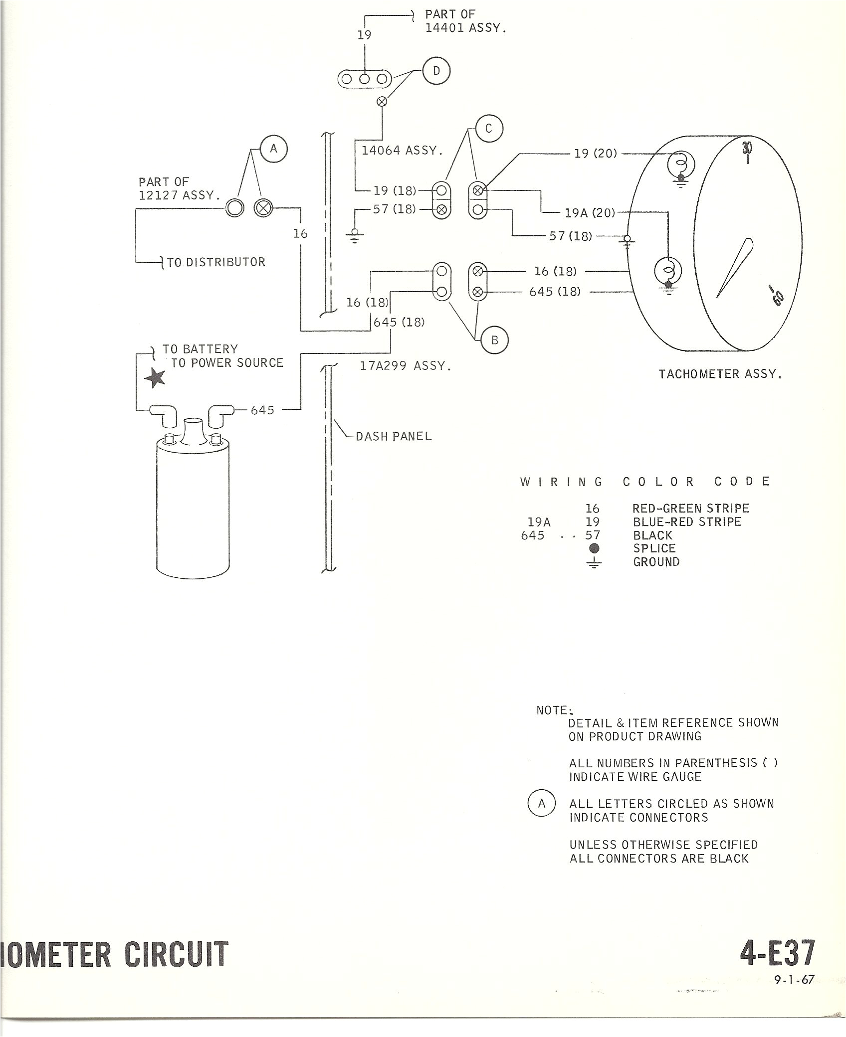
0 5 mustang tach wiring wiring diagram mega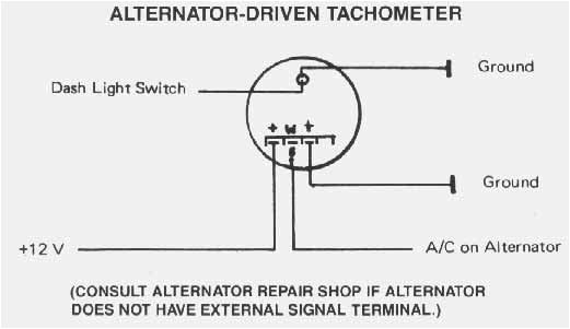
vdo tach wiring wiring diagram basic
vdo rev counter wiring diagram diagram vdo rev counter wiring diagram posted on june 20 2018 by admin unusual vdo tachometer wiring diagram 1 min contemporary simple figure 4 17 dual synchronous rotor tachometer wiring diagram alternator driven tachometer old fashioned vdo tach gen wiring diagram composition everything rev counter for mopeds schematic 62206 circuit and rev counter for mopeds schematic circuit and wiring diagram download for automotive car motorcycle truck audio radio electronic devices home and house appliances published on 07 jul 2014 parts and accessories installation instructions motoringfile en 8 retrofit kit 62 11 0 030 110 installation instructions no 01 29 0 138 899 issue date 07 2001 5 to install and connect the rev counter wiring harness vdo rev counter wiring diagram wiringall com chometer as shown in diagram b tighten run wires from the tachometer loca proper wiring of the vdo programmable tachometer with typical ignition 12 ebay tachometer wiring diagram explained mini bike scooter wiring configuration is different than most tachometers 20150213 200330 wiring rev counter problems questions and technical wiring rev counter posted in problems questions and technical model mayfairyear 1989i recently brought myself a new rev counter after i couldnt get the old one to worknow this is were i need you clever peoples help i dont have the foggyest how to wire it in now im guessing the black is my earth and also were do the rest go and i also rev counter wiring problems questions and technical rev counter wiring posted in problems questions and technical hi all currently fitting a nice old smiths rev counter to the mini its a 1987 so just three wires switched live coil and earth fitted it but it didnt move at all its an rvc so should work and has a good earth when i checked the wires with a voltmeter the light green st200 clubman tachometer stack limited for the serious performance enthusiast the 80mm sized st200 clubman tachometer features the unique extremely rugged stack stepper motor movement with digital quartz accuracy for unparalleled precision tachometer installation and before cutting any holes rev instructions for the installation and operation of the programmable tachometer are contained herein use is restricted to 12 volt or 24 volt negative ground electrical systems c diagram d proper wiring of the tachometer with ignition electronic control box alternator generator and inductive senders diesel applications ˇ ˆ ˇ ˆˆ c installation instructions 5 tachometer 12v ba ttery installation instructions 5 tachometer 2650 1244 00 rev b questions if after completely reading these instructions you have questions regarding the operation or installation of your instrument s
