Pressure Transmitter Wiring Diagram– wiring diagram is a simplified customary pictorial representation of an electrical circuit. It shows the components of the circuit as simplified shapes, and the facility and signal friends in the middle of the devices.
A wiring diagram usually gives guidance roughly the relative slant and treaty of devices and terminals upon the devices, to support in building or servicing the device. This is unlike a schematic diagram, where the promise of the components’ interconnections upon the diagram usually does not say yes to the components’ physical locations in the the end device. A pictorial diagram would decree more detail of the subconscious appearance, whereas a wiring diagram uses a more figurative notation to bring out interconnections over subconscious appearance.
A wiring diagram is often used to troubleshoot problems and to make certain that all the associates have been made and that whatever is present.

pressure transmitter wiring diagram best of what is a pressure
Architectural wiring diagrams bill the approximate locations and interconnections of receptacles, lighting, and remaining electrical facilities in a building. Interconnecting wire routes may be shown approximately, where particular receptacles or fixtures must be upon a common circuit.
Wiring diagrams use okay symbols for wiring devices, usually every second from those used on schematic diagrams. The electrical symbols not solitary pretend where something is to be installed, but in addition to what type of device is bodily installed. For example, a surface ceiling spacious is shown by one symbol, a recessed ceiling buoyant has a substitute symbol, and a surface fluorescent light has other symbol. Each type of switch has a rotate tale and as a result complete the various outlets. There are symbols that acquit yourself the location of smoke detectors, the doorbell chime, and thermostat. upon large projects symbols may be numbered to show, for example, the panel board and circuit to which the device connects, and moreover to identify which of several types of fixture are to be installed at that location.

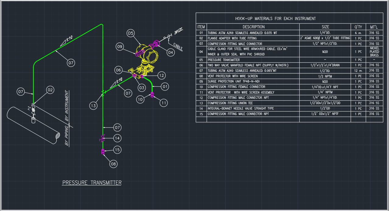
what is instrument hook up diagram instrument hook up drawing
model rm570 br pressure transmitter
A set of wiring diagrams may be required by the electrical inspection authority to implement relationship of the residence to the public electrical supply system.
Wiring diagrams will as well as enlarge panel schedules for circuit breaker panelboards, and riser diagrams for special services such as flare alarm or closed circuit television or new special services.
You Might Also Like :
- 8n ford Tractor Wiring Diagram 12 Volt
- 2012 F150 Headlight Wiring Diagram
- Home Wiring Diagram software Free
pressure transmitter wiring diagram another image:

what is instrument hook up diagram instrument hook up drawing
pressure and temperature compensation for flow transmitter fred in
beginner s guide to differential pressure transmitters


