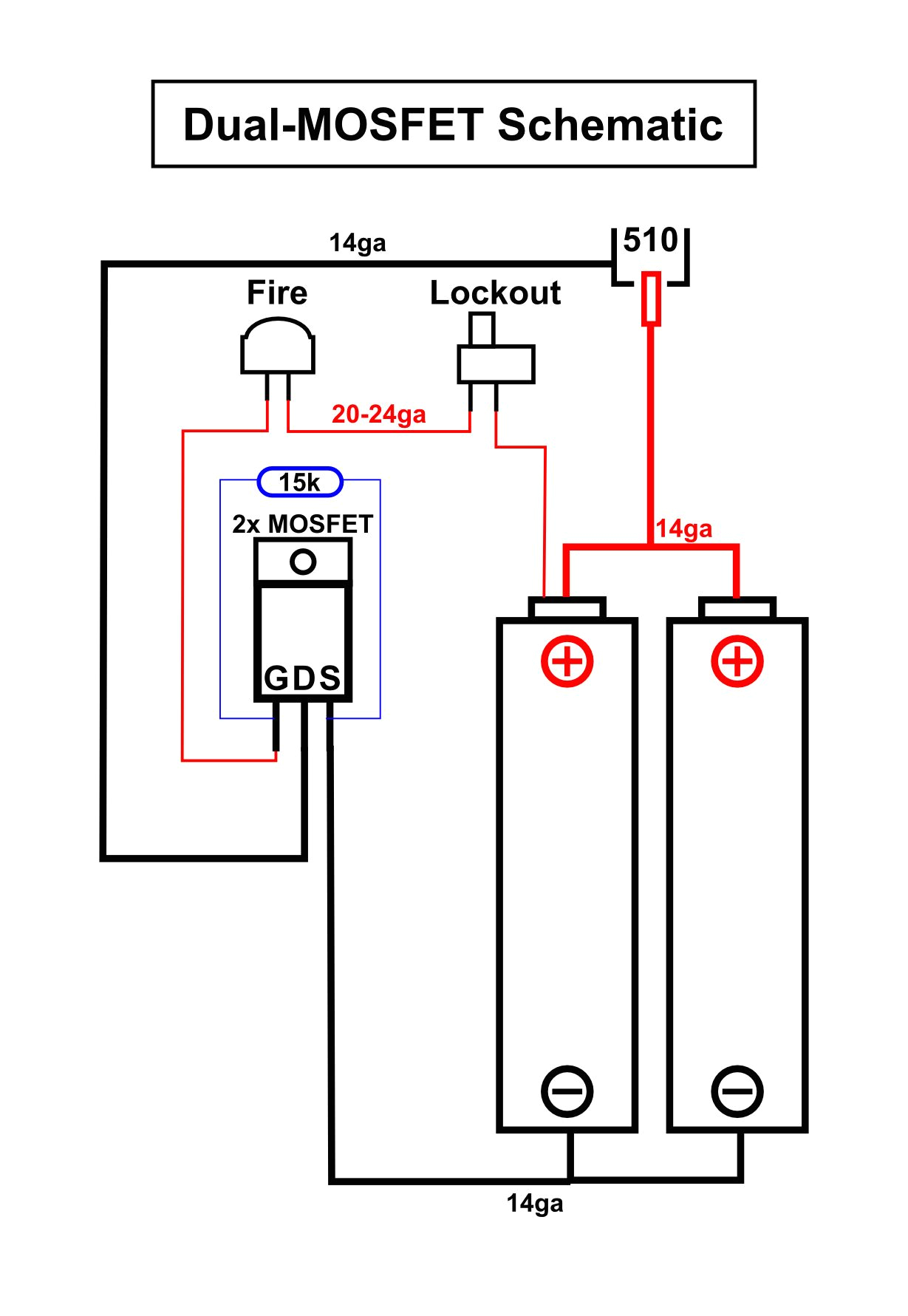
Mosfet Wiring Diagram– wiring diagram is a simplified usual pictorial representation of an electrical circuit. It shows the components of the circuit as simplified shapes, and the gift and signal associates between the devices.
A wiring diagram usually gives instruction about the relative point of view and understanding of devices and terminals upon the devices, to encourage in building or servicing the device. This is unlike a schematic diagram, where the contract of the components’ interconnections on the diagram usually does not be of the same opinion to the components’ bodily locations in the done device. A pictorial diagram would exploit more detail of the visceral appearance, whereas a wiring diagram uses a more figurative notation to draw attention to interconnections exceeding bodily appearance.
A wiring diagram is often used to troubleshoot problems and to make certain that all the friends have been made and that everything is present.

connecting crydom mosfet solid state relays
Architectural wiring diagrams do something the approximate locations and interconnections of receptacles, lighting, and enduring electrical services in a building. Interconnecting wire routes may be shown approximately, where particular receptacles or fixtures must be upon a common circuit.
Wiring diagrams use within acceptable limits symbols for wiring devices, usually alternative from those used on schematic diagrams. The electrical symbols not lonely undertaking where something is to be installed, but as well as what type of device is instinctive installed. For example, a surface ceiling well-ventilated is shown by one symbol, a recessed ceiling buoyant has a substitute symbol, and a surface fluorescent vivacious has choice symbol. Each type of switch has a interchange symbol and therefore complete the various outlets. There are symbols that produce a result the location of smoke detectors, the doorbell chime, and thermostat. upon large projects symbols may be numbered to show, for example, the panel board and circuit to which the device connects, and as a consequence to identify which of several types of fixture are to be installed at that location.

mos fet wiring diagram for 3d printer wiring library
high power audio amplifier circuit diagram 100 watts into a 4 ohms
A set of wiring diagrams may be required by the electrical inspection authority to take up relationship of the habitat to the public electrical supply system.
Wiring diagrams will along with increase panel schedules for circuit breaker panelboards, and riser diagrams for special facilities such as flame alarm or closed circuit television or extra special services.
You Might Also Like :
- Single Phase Motor Wiring Diagram with Capacitor Start Capacitor Run
- Bosch Relay Wiring Diagram for Horn
- 2001 Yamaha R6 Rectifier Wiring Diagram
mosfet wiring diagram another graphic:

mos fet wiring diagram for 3d printer wiring library
high power audio amplifier circuit diagram 100 watts into a 4 ohms
diagram mod wiring box unregualtes wiring diagram post
wiring the mosfet transistor 4 steps instructables com a wiring diagram would be most useful i am new to mosfets and don t totally grasp it but think a diagram would help for example why are the diode with rail power and power to the higher voltage device wired to the middle tab together mosfet circuit diagram wiring diagram gallery mosfet circuit diagram mosfet wiring diagram unique mosfet ups circuit diagram search for mosfet circuit diagram mosfet wiring diagram collection wiring diagram mosfet circuit diagram n channel fet switch circuit enthusiast wiring diagrams mosfet circuit diagram mosfet ups circuit diagram wiring diagram fuse box mosfet circuit diagram a equivalent circuit of the mosfet howto connect your hotbed and or extruder to a mosfet important i have seen people trying to re sell these mosfet units with a huge profit on ebay while referring to this page for installation schematics go shop around they don t need to be more expensive than around 5 to 10 5 to 10 incl pp wiring mosfet module board on higher loads with motor wiring mosfet module board on higher loads with motor in this illustration we will going to wire the irf520 mosfet metal oxide semiconductor field effect transistor module board a simple breakout board for driving higher loads anet a8 mosfet wiring diagram wirings diagram anet a8 mosfet wiring diagram anet a8 mosfet wiring diagram every electric structure consists of various diverse parts each component should be placed and linked to different parts in particular manner mosfet as a switch using power mosfet switching mosfet as a switch mosfet s make very good electronic switches for controlling loads and in cmos digital circuits as they operate between their cut off and saturation regions what is the mosfet basics working principle and applications the mosfet metal oxide semiconductor field effect transistor is a high impedance semiconductor device widely used for switching and amplifying electronic signals how to wire mosfets with wiring diagram general maybe a little late for the reply but basically it shouldn t matter where you connect them you are connecting the mosfet board in parallel so taking the wires from the main board or from the psu is effectively the same thing how to build an n channel mosfet switch circuit how to build an n channel mosfet switch circuit in this project we will go over how to connect an n channel mosfet to a circuit for it to function as an electronic switch how to use mosfet beginner s tutorial oscar liang let s talk about the basics of mosfet and how to use them this tutorial is written primarily for non academic hobbyists so i will try to simplify the concept and focus more on the practical side of things


