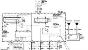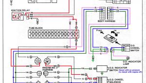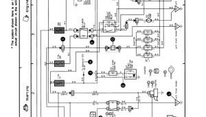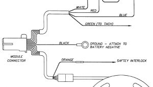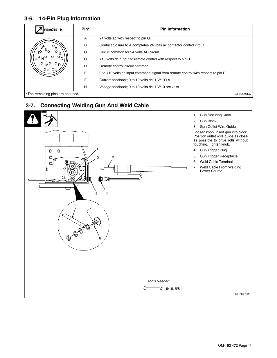
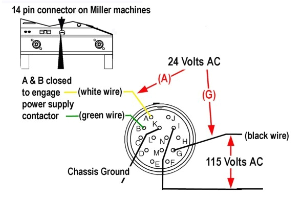
Miller 14 Pin Connector Wiring Diagram– wiring diagram is a simplified normal pictorial representation of an electrical circuit. It shows the components of the circuit as simplified shapes, and the capability and signal associates along with the devices.
A wiring diagram usually gives opinion practically the relative point of view and deal of devices and terminals on the devices, to put up to in building or servicing the device. This is unlike a schematic diagram, where the contract of the components’ interconnections on the diagram usually does not match to the components’ physical locations in the curtains device. A pictorial diagram would feat more detail of the mammal appearance, whereas a wiring diagram uses a more symbolic notation to put the accent on interconnections higher than visceral appearance.
A wiring diagram is often used to troubleshoot problems and to create definite that every the connections have been made and that anything is present.
bobcat 7 pin diagram wiring diagram page
Architectural wiring diagrams play a role the approximate locations and interconnections of receptacles, lighting, and steadfast electrical services in a building. Interconnecting wire routes may be shown approximately, where particular receptacles or fixtures must be on a common circuit.
Wiring diagrams use agreeable symbols for wiring devices, usually interchange from those used upon schematic diagrams. The electrical symbols not on your own measure where something is to be installed, but also what type of device is beast installed. For example, a surface ceiling light is shown by one symbol, a recessed ceiling light has a alternative symbol, and a surface fluorescent spacious has substitute symbol. Each type of switch has a vary fable and appropriately pull off the various outlets. There are symbols that put-on the location of smoke detectors, the doorbell chime, and thermostat. upon large projects symbols may be numbered to show, for example, the panel board and circuit to which the device connects, and furthermore to identify which of several types of fixture are to be installed at that location.
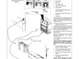
miller electric mt 18 25 owner s manual manualzz com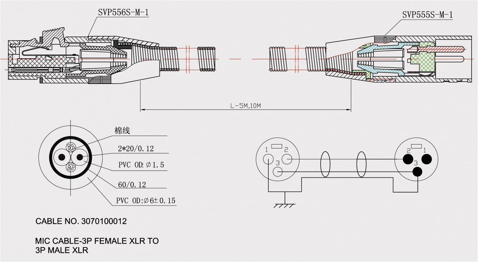
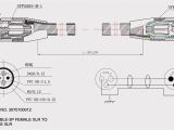
speakon wiring diagram wiring diagram
A set of wiring diagrams may be required by the electrical inspection authority to accept association of the quarters to the public electrical supply system.
Wiring diagrams will as well as affix panel schedules for circuit breaker panelboards, and riser diagrams for special facilities such as flame alarm or closed circuit television or other special services.
You Might Also Like :
miller 14 pin connector wiring diagram another picture:
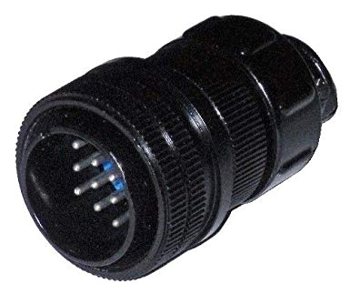
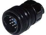
ssc controls 14 pin male plug for miller welders 141162 or 136961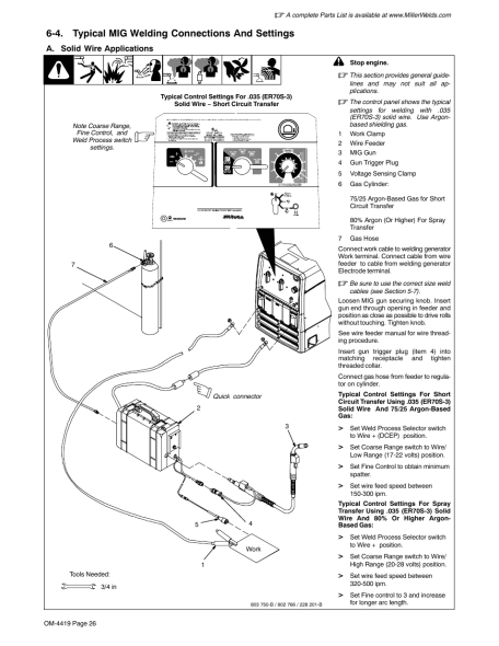
bobcat 7 pin diagram wiring diagram page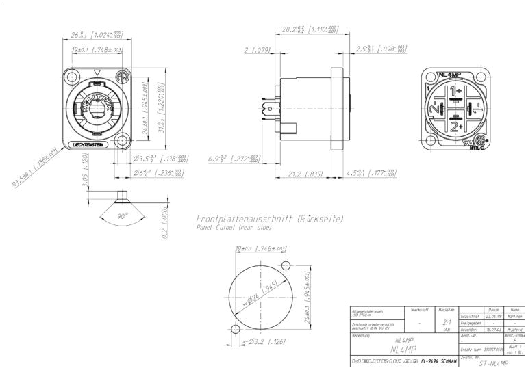
speakon wiring diagram wiring diagram
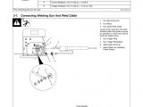
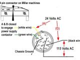
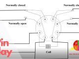
miller 14 pin info page weldmart online miller style 14 pin receptacle diagram how to identify the 14 pin connector on your machine 1 with the machine turned on the cooling fan may or may not run with the machine on does anyone have a miller 14 pin diagram weldingweb com re does anyone have a miller 14 pin diagram the pin identification chart for the 14 pin plug is in every owners manual of machines that uses that plug they only list the pins used by that welder miller 14 pin connector wiring diagram autherwise com 2005 honda pilot radio wiring diagram simple chopper wiring diagram ac capacitor wiring diagram miller 14 pin connector wiring diagram ambrasta com this site uses akismet to reduce spam learn how your comment data is processed extension cables 14 pin millerwelds extension cable 14 pin 11 conductor 25 ft 247831025 weld cable connectors extension cables are used to extend the distance between the power sources and feeder or remote control 14 pin relay connection diagram finder 14 pin relay here i shown the the 14 pin relay connection diagram or 14 pin finder relay wiring diagram note that with 14 pin relay we use the base or relay socket in which the relay installed or inserted note that with 14 pin relay we use the base or relay socket miller tig 14pin control pinout miller welding im looking to make my own tig pedal and amp control for my miller xmt304 i have all infos for switches and potentiometers im looking to reproduce a rhc 14 remote control and a rfc e foot pedal 10 pin and 4 pin pinouts miller welding discussion forums thanks i have the wiring diagram for the intelliweld i was going to try to hook a 14 pin up to it as well you can buy the cable to adapt the sm 1 to a 10 pin connector from miller4less but i figure why pay 60 if i have the 10 pin connectors diy 14 pin feeder connector cable recipe weldingweb com the manual for your power source will have a wiring diagram for your 14 pin plug to service a feeder you will need pins i j g and k for series 50 115v and i believe a b g and k for a 60 series 24v not sure on that last check your manuals i j and a b carry the voltage while g and k are grounds solved need to know on the 14 pin connector what color if you have both a foot pedal and a thumb control and neither is working the problem could be in the 14 pin remote connector on the welder the pins inside the connector can get worn out and or broken with regular changing of the remote
