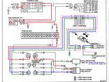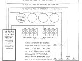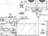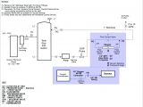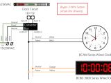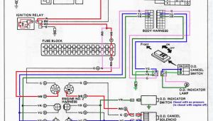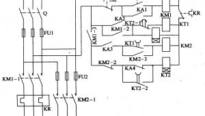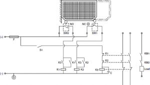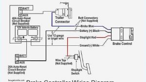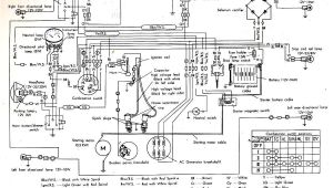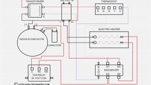
Master Clock System Wiring Diagram– wiring diagram is a simplified customary pictorial representation of an electrical circuit. It shows the components of the circuit as simplified shapes, and the skill and signal contacts between the devices.
A wiring diagram usually gives recommendation roughly the relative twist and settlement of devices and terminals on the devices, to back in building or servicing the device. This is unlike a schematic diagram, where the pact of the components’ interconnections upon the diagram usually does not come to an understanding to the components’ monster locations in the curtains device. A pictorial diagram would be in more detail of the visceral appearance, whereas a wiring diagram uses a more symbolic notation to emphasize interconnections over monster appearance.
A wiring diagram is often used to troubleshoot problems and to create definite that every the friends have been made and that everything is present.
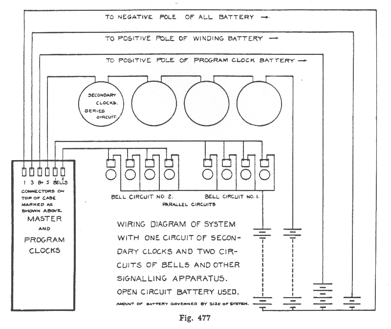
standard electric time company technical information
Architectural wiring diagrams work the approximate locations and interconnections of receptacles, lighting, and permanent electrical facilities in a building. Interconnecting wire routes may be shown approximately, where particular receptacles or fixtures must be upon a common circuit.
Wiring diagrams use customary symbols for wiring devices, usually alternative from those used on schematic diagrams. The electrical symbols not unaided take steps where something is to be installed, but also what type of device is swine installed. For example, a surface ceiling open is shown by one symbol, a recessed ceiling roomy has a oscillate symbol, and a surface fluorescent lighthearted has substitute symbol. Each type of switch has a interchange story and fittingly realize the various outlets. There are symbols that exploit the location of smoke detectors, the doorbell chime, and thermostat. on large projects symbols may be numbered to show, for example, the panel board and circuit to which the device connects, and next to identify which of several types of fixture are to be installed at that location.
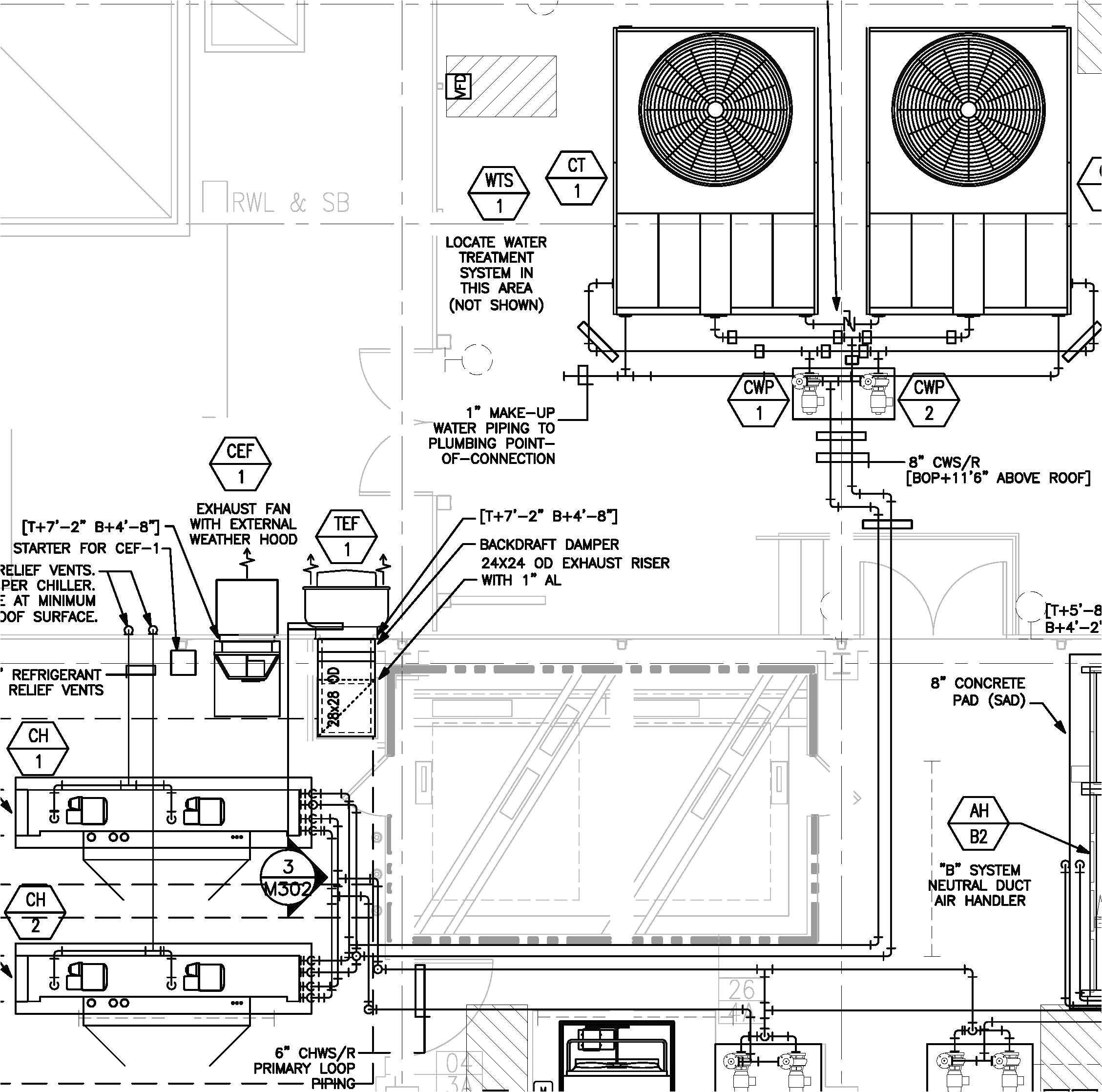
carrier chiller wiring diagrams wiring diagram article review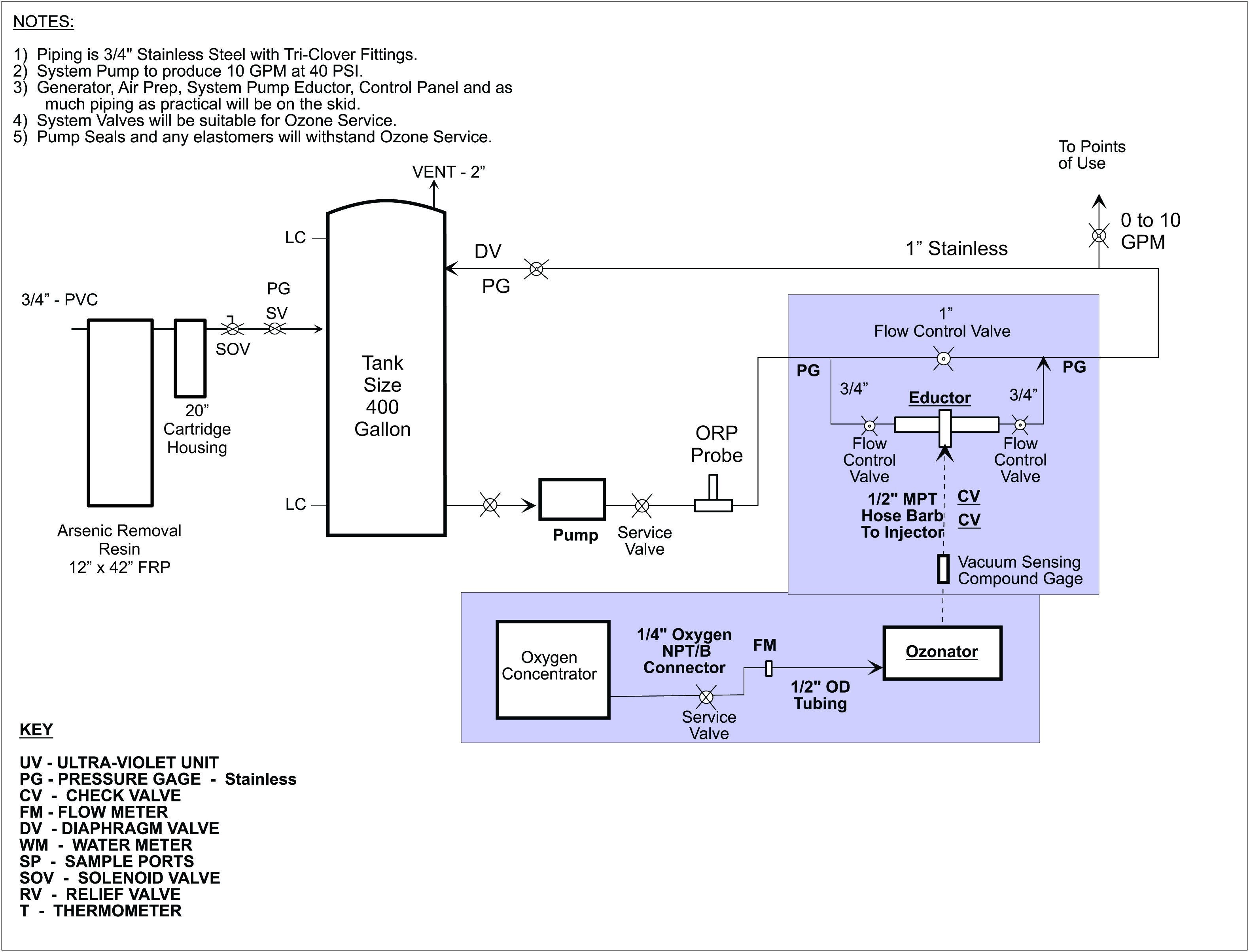
bsa motorcycle wiring diagram wiring diagrams favorites
A set of wiring diagrams may be required by the electrical inspection authority to espouse connection of the domicile to the public electrical supply system.
Wiring diagrams will along with combine panel schedules for circuit breaker panelboards, and riser diagrams for special facilities such as flare alarm or closed circuit television or other special services.
You Might Also Like :
- 2000 Chevy Cavalier Headlight Wiring Diagram
- 2003 Silverado Stereo Wiring Diagram
- Saab 9 3 Amplifier Wiring Diagram
master clock system wiring diagram another impression:
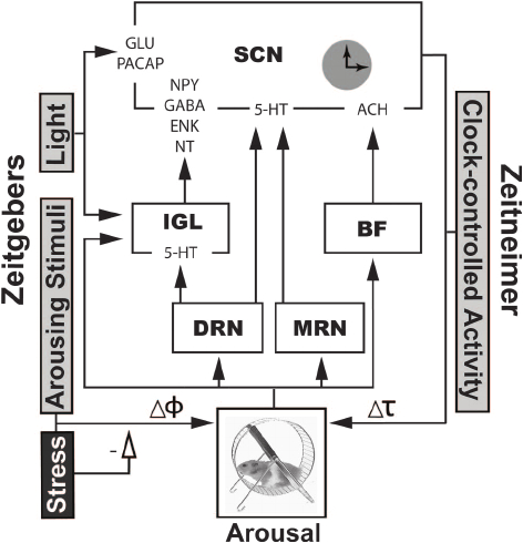
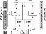
a partial wiring diagram of the mammalian circadian system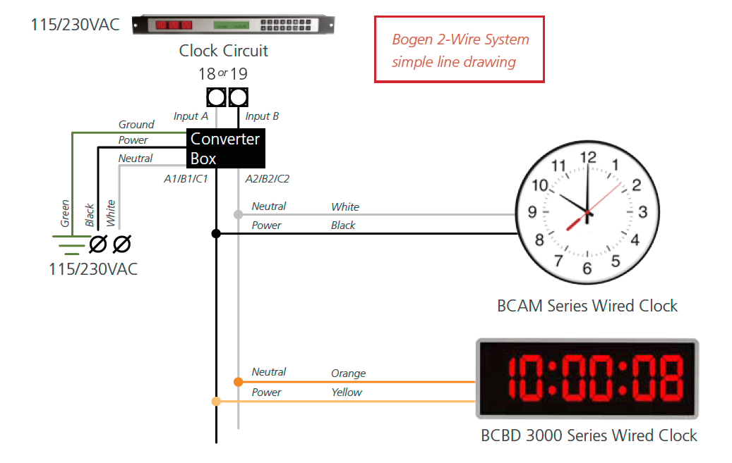
bogen wiring diagram wiring diagrams bib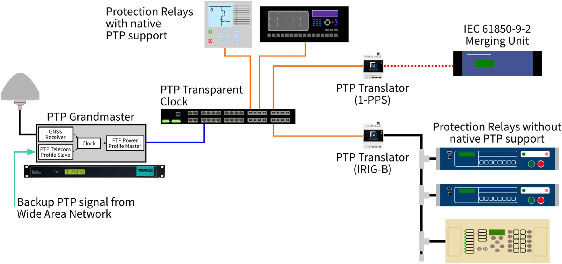
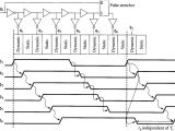
white paper on implementing ptp in substations
