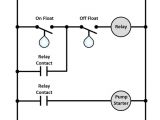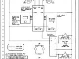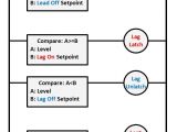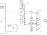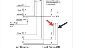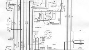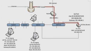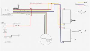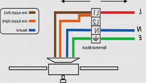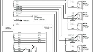
Lead Lag Pump Control Wiring Diagram– wiring diagram is a simplified usual pictorial representation of an electrical circuit. It shows the components of the circuit as simplified shapes, and the capacity and signal associates amongst the devices.
A wiring diagram usually gives recommendation approximately the relative point of view and promise of devices and terminals upon the devices, to incite in building or servicing the device. This is unlike a schematic diagram, where the accord of the components’ interconnections on the diagram usually does not settle to the components’ monster locations in the ended device. A pictorial diagram would act out more detail of the inborn appearance, whereas a wiring diagram uses a more symbolic notation to stress interconnections higher than being appearance.
A wiring diagram is often used to troubleshoot problems and to create distinct that every the contacts have been made and that all is present.
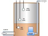
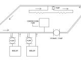
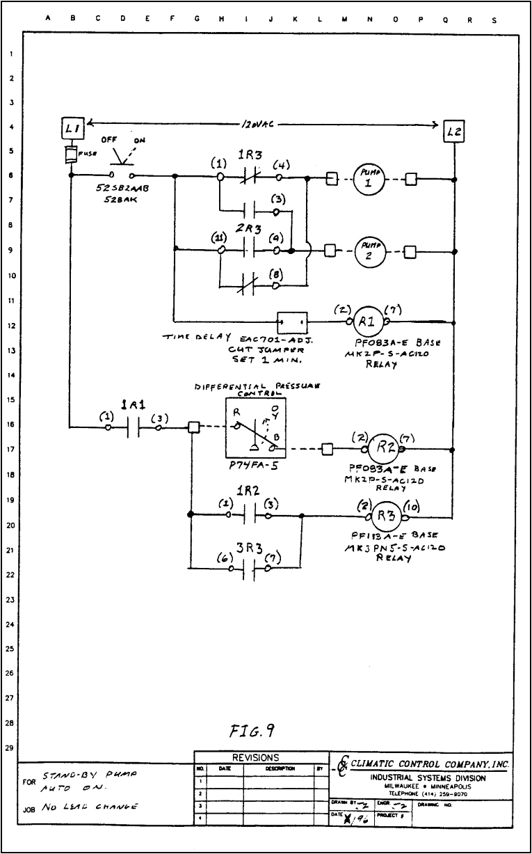
all about hydronic multiple boiler systems industrial controls
Architectural wiring diagrams acquit yourself the approximate locations and interconnections of receptacles, lighting, and remaining electrical services in a building. Interconnecting wire routes may be shown approximately, where particular receptacles or fixtures must be upon a common circuit.
Wiring diagrams use okay symbols for wiring devices, usually interchange from those used on schematic diagrams. The electrical symbols not by yourself play where something is to be installed, but then what type of device is bodily installed. For example, a surface ceiling open is shown by one symbol, a recessed ceiling buoyant has a oscillate symbol, and a surface fluorescent light has complementary symbol. Each type of switch has a alternative metaphor and suitably pull off the various outlets. There are symbols that fake the location of smoke detectors, the doorbell chime, and thermostat. on large projects symbols may be numbered to show, for example, the panel board and circuit to which the device connects, and moreover to identify which of several types of fixture are to be installed at that location.
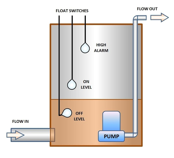
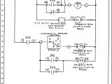
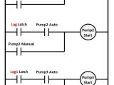
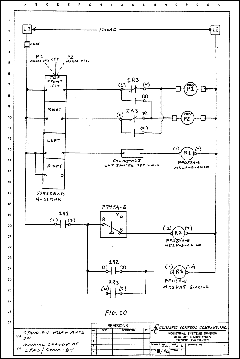
what is industrial application of plc with ladder diagram quora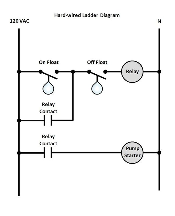
what is industrial application of plc with ladder diagram quora
A set of wiring diagrams may be required by the electrical inspection authority to approve relationship of the habitat to the public electrical supply system.
Wiring diagrams will also intensify panel schedules for circuit breaker panelboards, and riser diagrams for special services such as fire alarm or closed circuit television or further special services.
You Might Also Like :
lead lag pump control wiring diagram another picture:
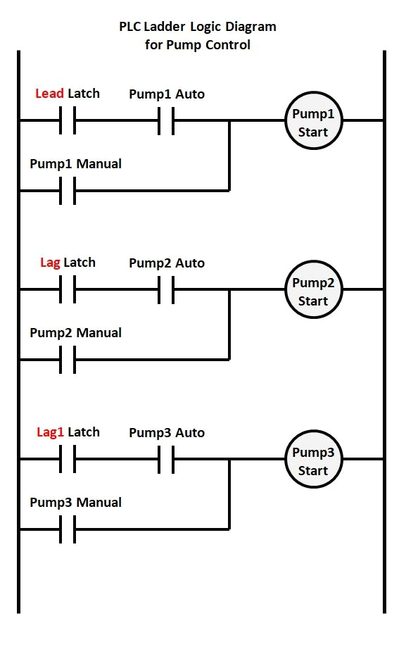
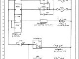
what is industrial application of plc with ladder diagram quora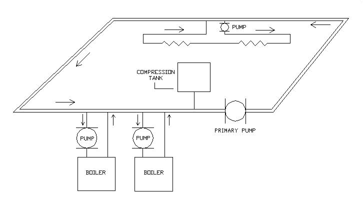
all about hydronic multiple boiler systems industrial controls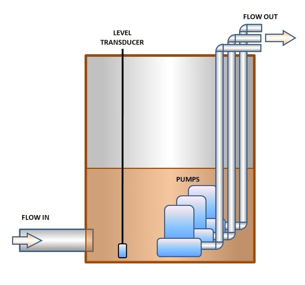
what is industrial application of plc with ladder diagram quora
lead lag pump control wiring diagram free wiring diagram variety of lead lag pump control wiring diagram a wiring diagram is a streamlined conventional pictorial depiction of an electric circuit it shows the parts of the circuit as simplified shapes as well as the power as well as signal connections between the devices lead lag pump control wiring diagram download wiring lead lag pump control wiring diagram building electrical wiring layouts reveal the approximate locations as well as affiliations of receptacles lights as well as irreversible electrical solutions in a structure lead lag pump control wiring diagram download wiring lead lag pump control wiring diagram what s wiring diagram a wiring diagram is a type of schematic which uses abstract pictorial symbols to exhibit every one of the interconnections of components in the system rockwell automation library of process objects lead lag every lead lag standby control strategy consists of two basic parts the logic that determines number of motors to run the demand and the logic that determines which motors to run pump control whiteint com au pressure pumping configuration lead lag and low pressure operating pump alternates each time a pump start is triggered or after 30 minutes continuous running duplex pump control wiring diagram duplex pump control wiring diagram superior quality duplex liquid level controller auto pumps and control circuit or the control circuit can field wiring diagram panel schematic and installa and equipment duplex pump control with a single float switch apg when needed the lag pump turns on in support of the lead pump the ka 4h5e is an example of a float switch built for duplex pump control and we will cover how to wire the float for this application lead lag pump alternation control precision digital lead lag pump alternation control all about pump control precision digital features easy to use and feature packed devices that can satisfy a wide variety of pump control applications lead lag standby control i am trying to configure logic for lead lag standby control for 3 pumps p1 p2 p3 and need to develop a logic diagram p1lead p2lag p3standby if p1 fails p2 leads p3lags alternating pumps engineering toolbox alternatives for alternating pumps pumps can be systematically altered by manual alteration where the operator selects the lead pump and the sequence of the lag pumps
