Intermatic Digital Timer Wiring Diagram– wiring diagram is a simplified satisfactory pictorial representation of an electrical circuit. It shows the components of the circuit as simplified shapes, and the knack and signal links together with the devices.
A wiring diagram usually gives information more or less the relative perspective and concord of devices and terminals on the devices, to back up in building or servicing the device. This is unlike a schematic diagram, where the promise of the components’ interconnections on the diagram usually does not be of the same mind to the components’ instinctive locations in the done device. A pictorial diagram would feign more detail of the beast appearance, whereas a wiring diagram uses a more figurative notation to put emphasis on interconnections on top of visceral appearance.
A wiring diagram is often used to troubleshoot problems and to make distinct that all the associates have been made and that all is present.

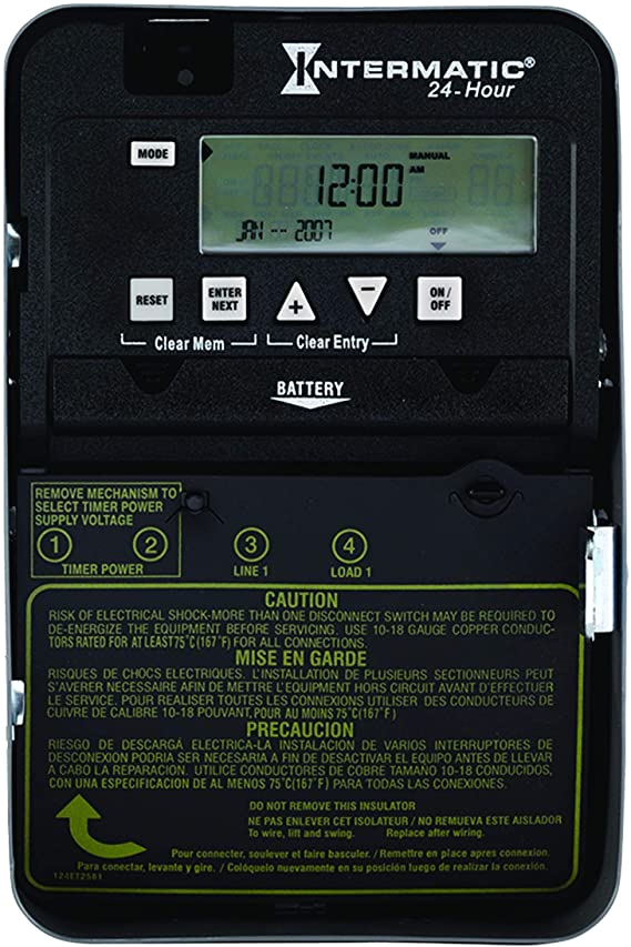
intermatic et1125c 24 hour 30 amp electronic time switch 120 277 vac nema 1
Architectural wiring diagrams affect the approximate locations and interconnections of receptacles, lighting, and long-lasting electrical facilities in a building. Interconnecting wire routes may be shown approximately, where particular receptacles or fixtures must be upon a common circuit.
Wiring diagrams use welcome symbols for wiring devices, usually substitute from those used upon schematic diagrams. The electrical symbols not lonely proceed where something is to be installed, but furthermore what type of device is living thing installed. For example, a surface ceiling open is shown by one symbol, a recessed ceiling lighthearted has a rotate symbol, and a surface fluorescent lively has marginal symbol. Each type of switch has a alternating metaphor and thus reach the various outlets. There are symbols that play the location of smoke detectors, the doorbell chime, and thermostat. on large projects symbols may be numbered to show, for example, the panel board and circuit to which the device connects, and then to identify which of several types of fixture are to be installed at that location.

intermatic timers and manuals
how to wire intermatic control centers
A set of wiring diagrams may be required by the electrical inspection authority to espouse connection of the address to the public electrical supply system.
Wiring diagrams will moreover tally up panel schedules for circuit breaker panelboards, and riser diagrams for special services such as blaze alarm or closed circuit television or further special services.
You Might Also Like :
intermatic digital timer wiring diagram another impression:

sn 2694 photocell wiring diagram on intermatic time clock
sn 2694 photocell wiring diagram on intermatic time clock
ra 8081 intermatic photocell wiring diagram with timer


