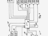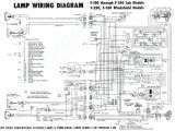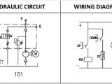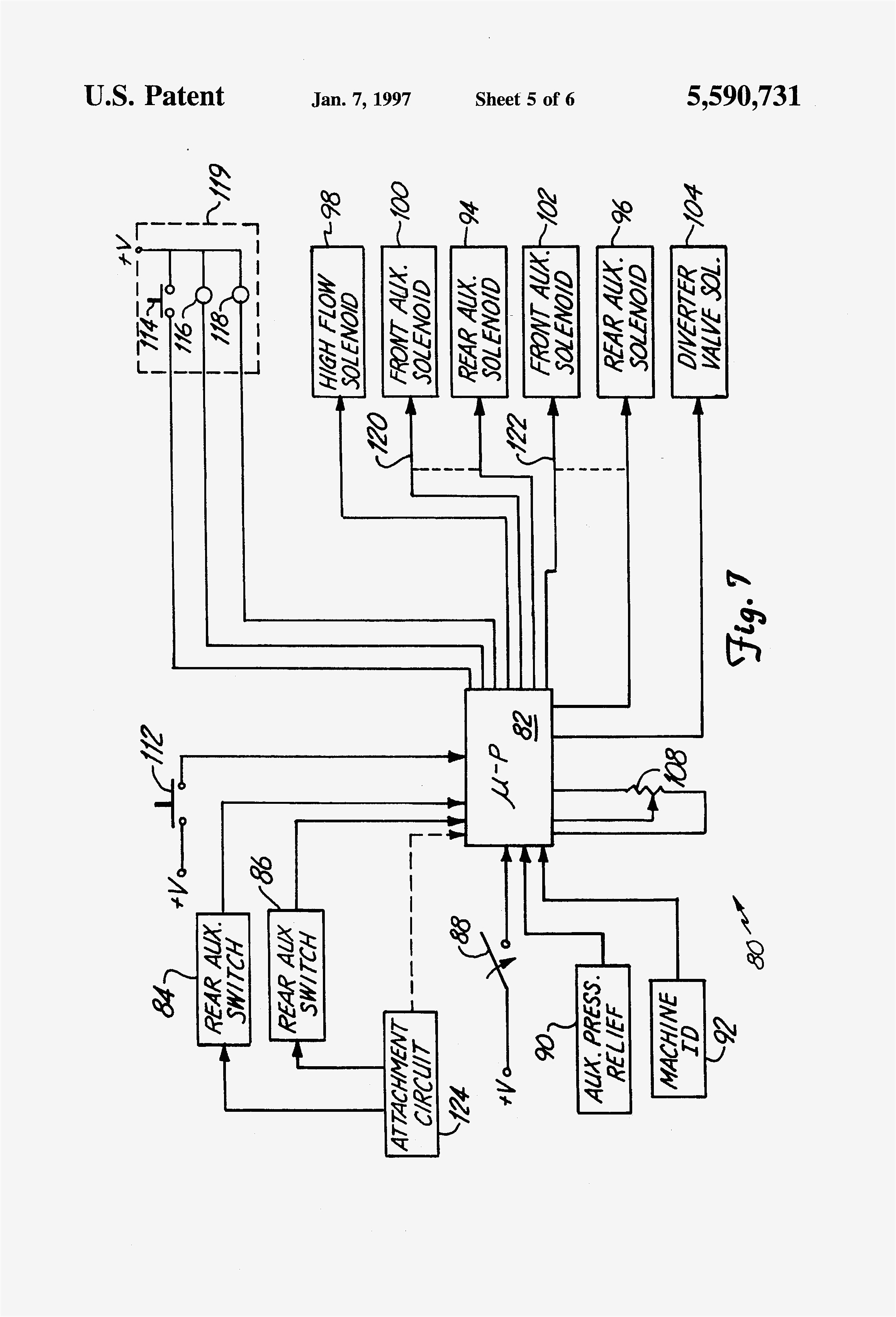
Hydraulic solenoid Wiring Diagram– wiring diagram is a simplified conventional pictorial representation of an electrical circuit. It shows the components of the circuit as simplified shapes, and the talent and signal friends surrounded by the devices.
A wiring diagram usually gives counsel about the relative incline and arrangement of devices and terminals on the devices, to back in building or servicing the device. This is unlike a schematic diagram, where the settlement of the components’ interconnections on the diagram usually does not go along with to the components’ creature locations in the ended device. A pictorial diagram would action more detail of the living thing appearance, whereas a wiring diagram uses a more figurative notation to emphasize interconnections more than beast appearance.
A wiring diagram is often used to troubleshoot problems and to create certain that all the links have been made and that all is present.
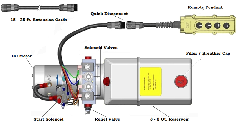
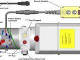
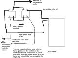
installation instructions 12 vdc dual double acting kti
Architectural wiring diagrams con the approximate locations and interconnections of receptacles, lighting, and long-lasting electrical facilities in a building. Interconnecting wire routes may be shown approximately, where particular receptacles or fixtures must be upon a common circuit.
Wiring diagrams use usual symbols for wiring devices, usually alternating from those used upon schematic diagrams. The electrical symbols not deserted behave where something is to be installed, but furthermore what type of device is monster installed. For example, a surface ceiling blithe is shown by one symbol, a recessed ceiling vivacious has a stand-in symbol, and a surface fluorescent light has unconventional symbol. Each type of switch has a swap parable and consequently do the various outlets. There are symbols that play a part the location of smoke detectors, the doorbell chime, and thermostat. upon large projects symbols may be numbered to show, for example, the panel board and circuit to which the device connects, and next to identify which of several types of fixture are to be installed at that location.
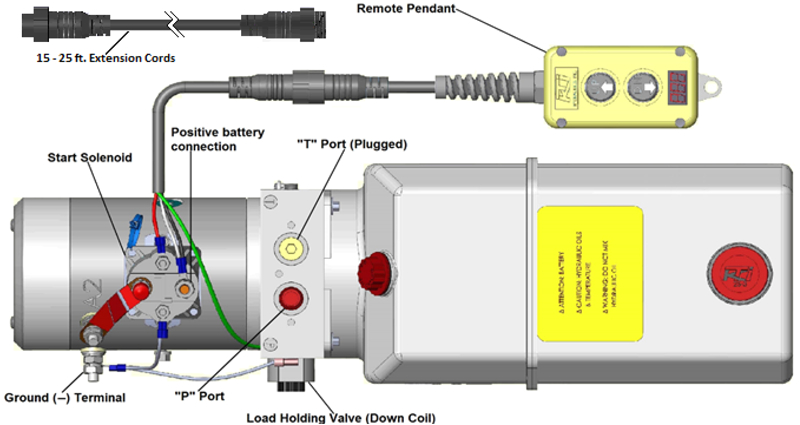
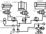
installation instructions 12 vdc single acting kti hydraulics inc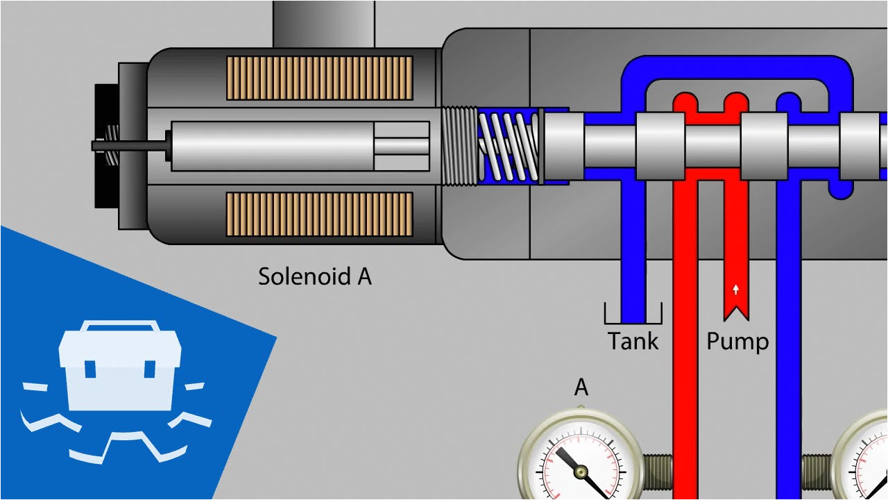
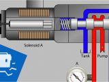
valve solenoid basics youtube
A set of wiring diagrams may be required by the electrical inspection authority to implement relationship of the residence to the public electrical supply system.
Wiring diagrams will also add together panel schedules for circuit breaker panelboards, and riser diagrams for special services such as blaze alarm or closed circuit television or additional special services.
You Might Also Like :
- Electrical Wiring Diagram software Free
- Shovelhead Wiring Diagram
- 7 Pin Ignition Module Wiring Diagram
hydraulic solenoid wiring diagram another photograph:
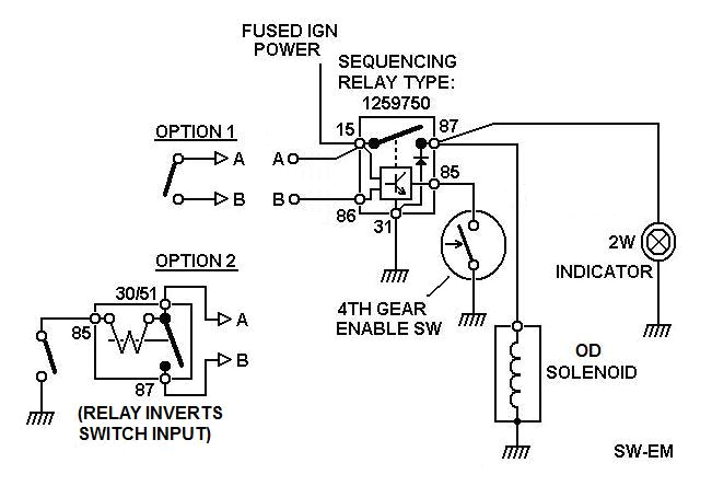
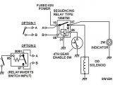
sw em od retrofitting on a vintage volvo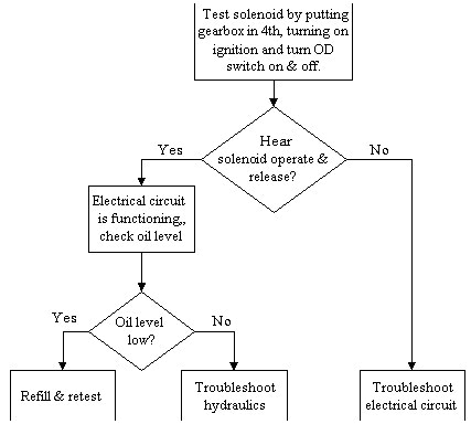
ezgo txt solenoid wiring diagram wiring diagram center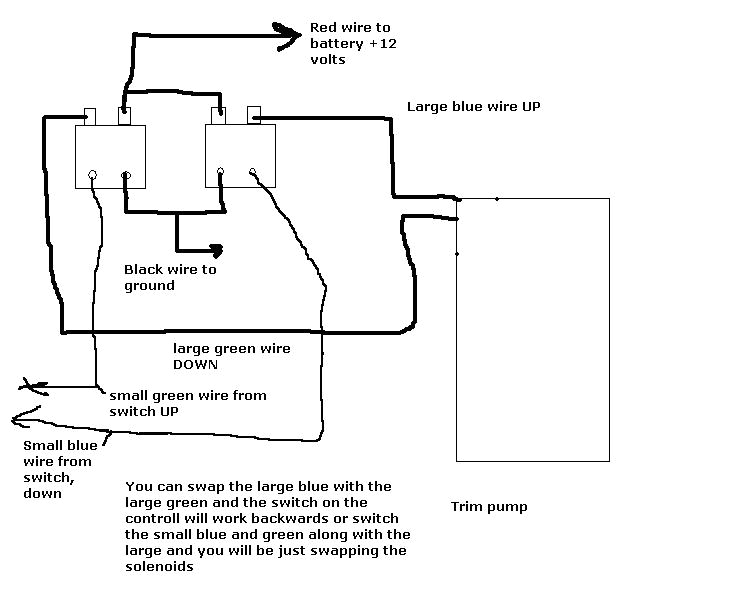
troubleshooting drive trims down but not up marine engines and
