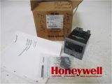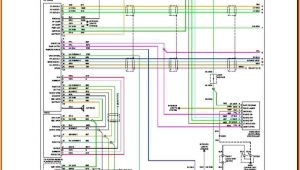
Honeywell M7284a1004 Wiring Diagram– wiring diagram is a simplified welcome pictorial representation of an electrical circuit. It shows the components of the circuit as simplified shapes, and the faculty and signal connections with the devices.
A wiring diagram usually gives counsel just about the relative viewpoint and conformity of devices and terminals on the devices, to back in building or servicing the device. This is unlike a schematic diagram, where the bargain of the components’ interconnections upon the diagram usually does not settle to the components’ living thing locations in the curtains device. A pictorial diagram would do its stuff more detail of the inborn appearance, whereas a wiring diagram uses a more figurative notation to make more noticeable interconnections more than monster appearance.
A wiring diagram is often used to troubleshoot problems and to make clear that every the connections have been made and that anything is present.
honeywell scanning mk9590 70a38 a a e a c c co a ae ae c ae oc µa a c
Architectural wiring diagrams operate the approximate locations and interconnections of receptacles, lighting, and steadfast electrical facilities in a building. Interconnecting wire routes may be shown approximately, where particular receptacles or fixtures must be on a common circuit.
Wiring diagrams use up to standard symbols for wiring devices, usually every other from those used on schematic diagrams. The electrical symbols not unaided do something where something is to be installed, but furthermore what type of device is brute installed. For example, a surface ceiling fresh is shown by one symbol, a recessed ceiling spacious has a alternative symbol, and a surface fluorescent light has substitute symbol. Each type of switch has a swing tale and thus complete the various outlets. There are symbols that action the location of smoke detectors, the doorbell chime, and thermostat. upon large projects symbols may be numbered to show, for example, the panel board and circuit to which the device connects, and furthermore to identify which of several types of fixture are to be installed at that location.
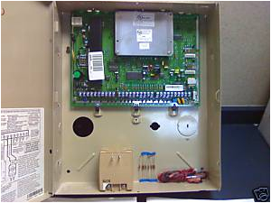
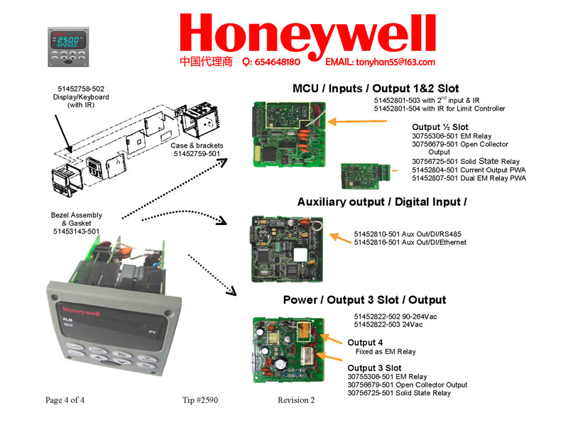
honeywell input board manufacturer in china by shfanghai
honeywell scanning mk9590 70a38 a a e a c c co a ae ae c ae oc µa a c
A set of wiring diagrams may be required by the electrical inspection authority to agree to relationship of the house to the public electrical supply system.
Wiring diagrams will moreover total panel schedules for circuit breaker panelboards, and riser diagrams for special facilities such as ember alarm or closed circuit television or further special services.
You Might Also Like :
- 2002 ford Taurus Stereo Wiring Diagram
- Electric Brewery Wiring Diagram
- Panasonic Cq Df583u Wiring Diagram
honeywell m7284a1004 wiring diagram another graphic:
honeywell scanning mk9590 70a38 a a e a c c co a ae ae c ae oc µa a c
section4 2 thermostat switch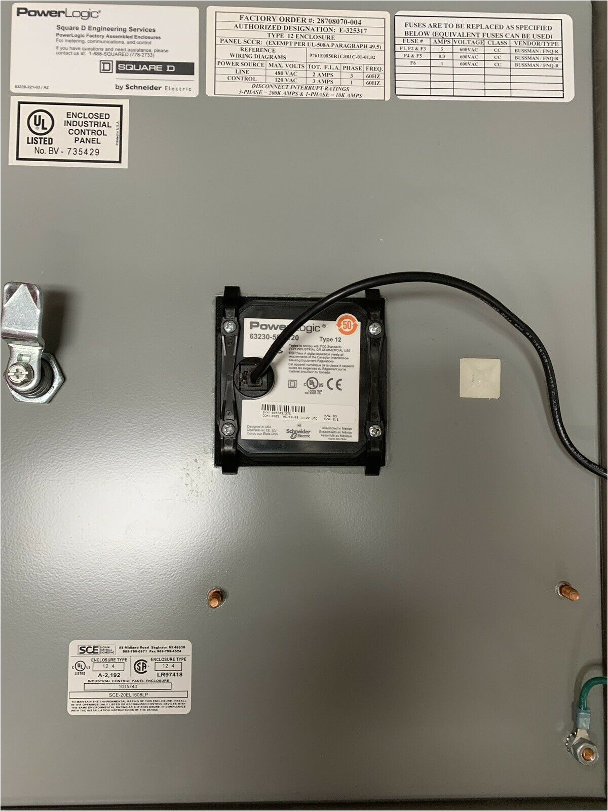
ion powerlogic ion7330 meter square d schneider ethergate
m7284a1004 u honeywell installation materials honeywell damper adjustment guide product data and specifications specification data for m7281 m7282 m7284 m7285 m7294 modutrol iv motors english product data and specifications china hazardous substance table english series 71 72 and 76 modutrol iv motors honeywell series 71 72 and 76 modutrol iv motors 63 2640 08 2 ordering information when purchasing replacement and modernization products from your tradeline wholesaler or distributor refer to the actuator wiring diagrams honeywell wiring diagrams actuator wiring diagrams direct coupled actuators non spring return models 160 direct coupled actuators non spring return models n05 series mn6105 mn7505 and n10 series mn6110 mn7510 wiring for floating control wiring for voltage control wiring for auxiliary switches floating dir 1 24 vac 1 2 2 line voltage power supply provide disconnect means and overload www buildingcontrols honeywell com www buildingcontrols honeywell com 63 2691 01 modutrol iv motor cross honeywell modutrol iv motor cross reference 3 63 2691 01 series 90 91 94 135 ohm three wire potentiometer input based on 135 ohm potentiometers found in controls such as l91 q181 q209 s963b t915 t991 and 63 2631 07 series 90 modutrol iv motors honeywell by using this honeywell literature you agree that honeywell will have no liability for any damages arising out of your use or modification to the literature you will defend and indemnify honeywell its affiliates and subsidiaries from and against any liability cost or damages modutrol motors model selection guide lesman modutrol motors model selection guide this chart is intended for selection purposes only for complete product application information refer to individual product specification sheets normal position model power supply voltage vac type of controller or input signal recommended timing sec stroke deg auxiliary switches mech elec torque series 61 and series 62 modutrol iv motors honeywell series 61 and series 62 modutrol iv motors application the series 61 and series 62 modutrol iv motors are three wire spring return and non spring return floating control motors use these motors with controllers that provide a switched spdt or floating output to operate dampers or valves the series 62 motors have an internal electrically isolated feedback potentiometer that provides honeywell l7224u1002 installation guide page 5 get honeywell l7224u1002 installation guide get all honeywell manuals how to wire a honeywell thermostat hunker the wiring for your honeywell thermostat depends on the functions of your heating and cooling system you ll probably see a thermostat jumper wire connecting the rc and rh terminals it s there so you can supply power to the heating and cooling switches with a single wire which is usually red
