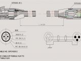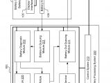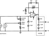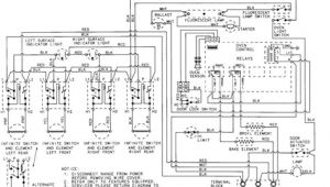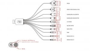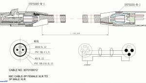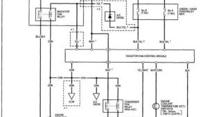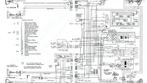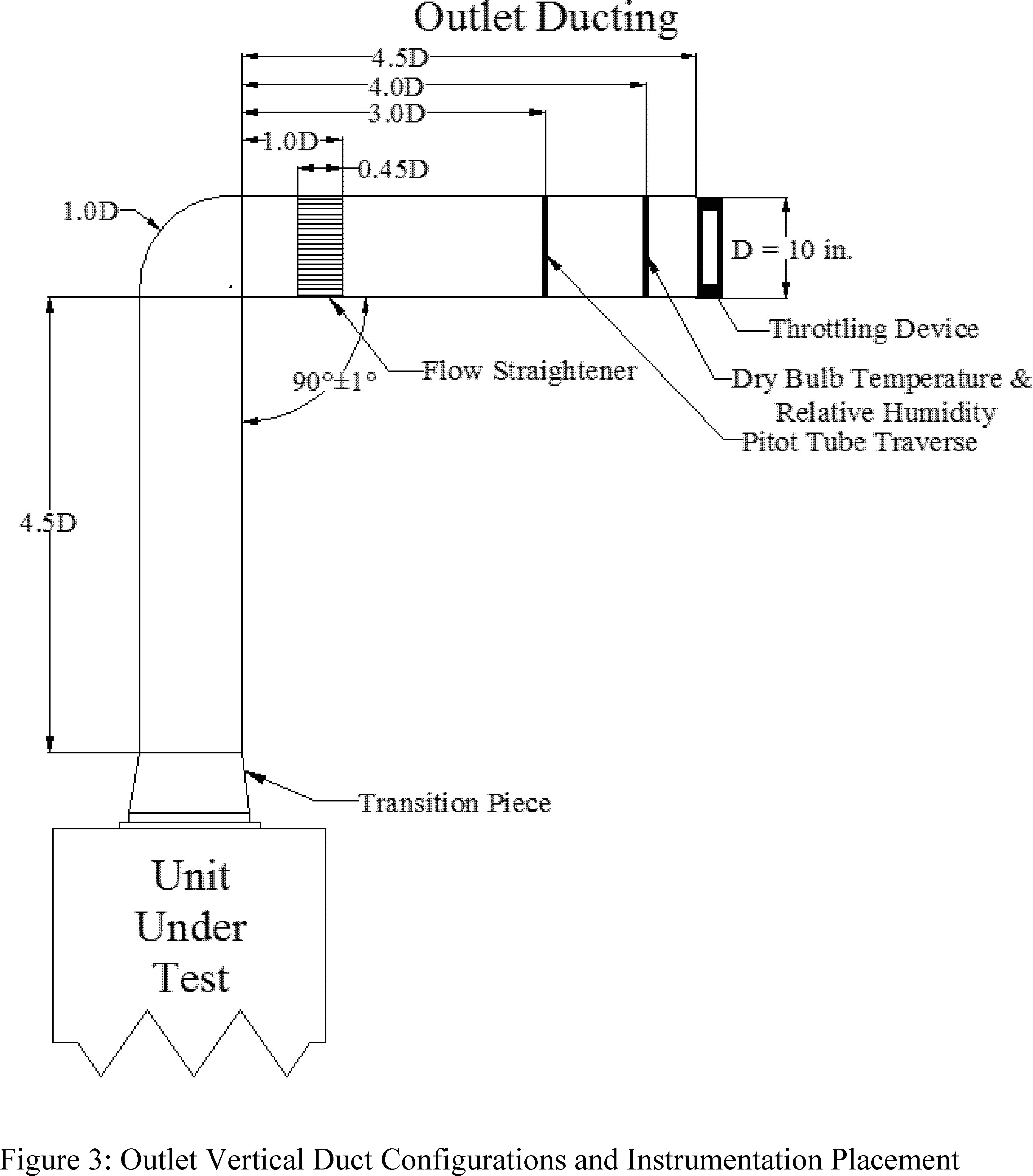
High Voltage Wiring Diagram– wiring diagram is a simplified satisfactory pictorial representation of an electrical circuit. It shows the components of the circuit as simplified shapes, and the capability and signal friends in the company of the devices.
A wiring diagram usually gives recommendation approximately the relative approach and settlement of devices and terminals on the devices, to encourage in building or servicing the device. This is unlike a schematic diagram, where the conformity of the components’ interconnections upon the diagram usually does not reach agreement to the components’ creature locations in the curtains device. A pictorial diagram would show more detail of the physical appearance, whereas a wiring diagram uses a more figurative notation to bring out interconnections greater than bodily appearance.
A wiring diagram is often used to troubleshoot problems and to make determined that all the associates have been made and that whatever is present.
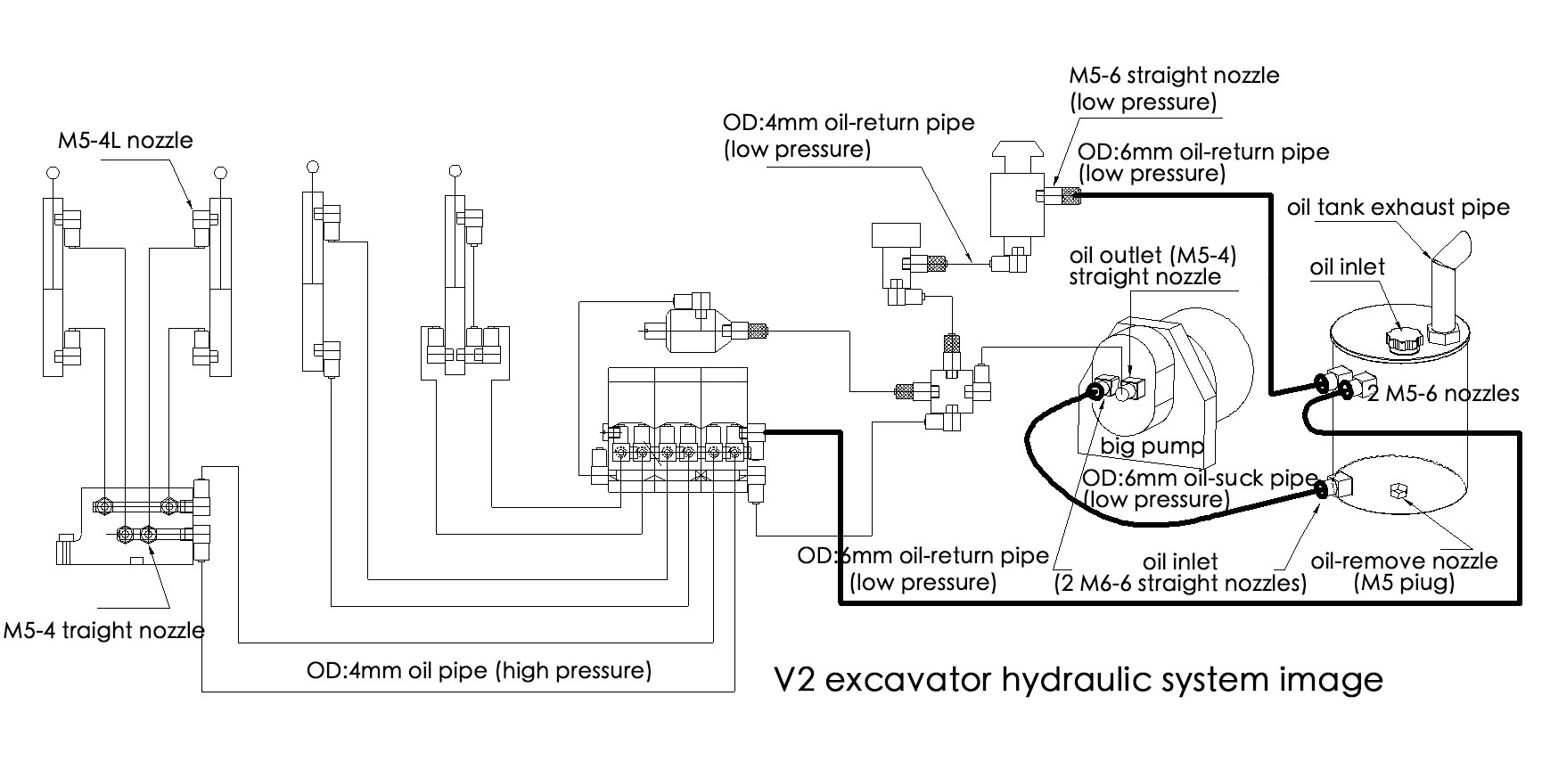
pump wiring diagram wiring diagram database
Architectural wiring diagrams be in the approximate locations and interconnections of receptacles, lighting, and enduring electrical facilities in a building. Interconnecting wire routes may be shown approximately, where particular receptacles or fixtures must be on a common circuit.
Wiring diagrams use standard symbols for wiring devices, usually swing from those used upon schematic diagrams. The electrical symbols not lonely measure where something is to be installed, but afterward what type of device is innate installed. For example, a surface ceiling spacious is shown by one symbol, a recessed ceiling open has a different symbol, and a surface fluorescent open has option symbol. Each type of switch has a alternative story and appropriately complete the various outlets. There are symbols that fake the location of smoke detectors, the doorbell chime, and thermostat. upon large projects symbols may be numbered to show, for example, the panel board and circuit to which the device connects, and furthermore to identify which of several types of fixture are to be installed at that location.
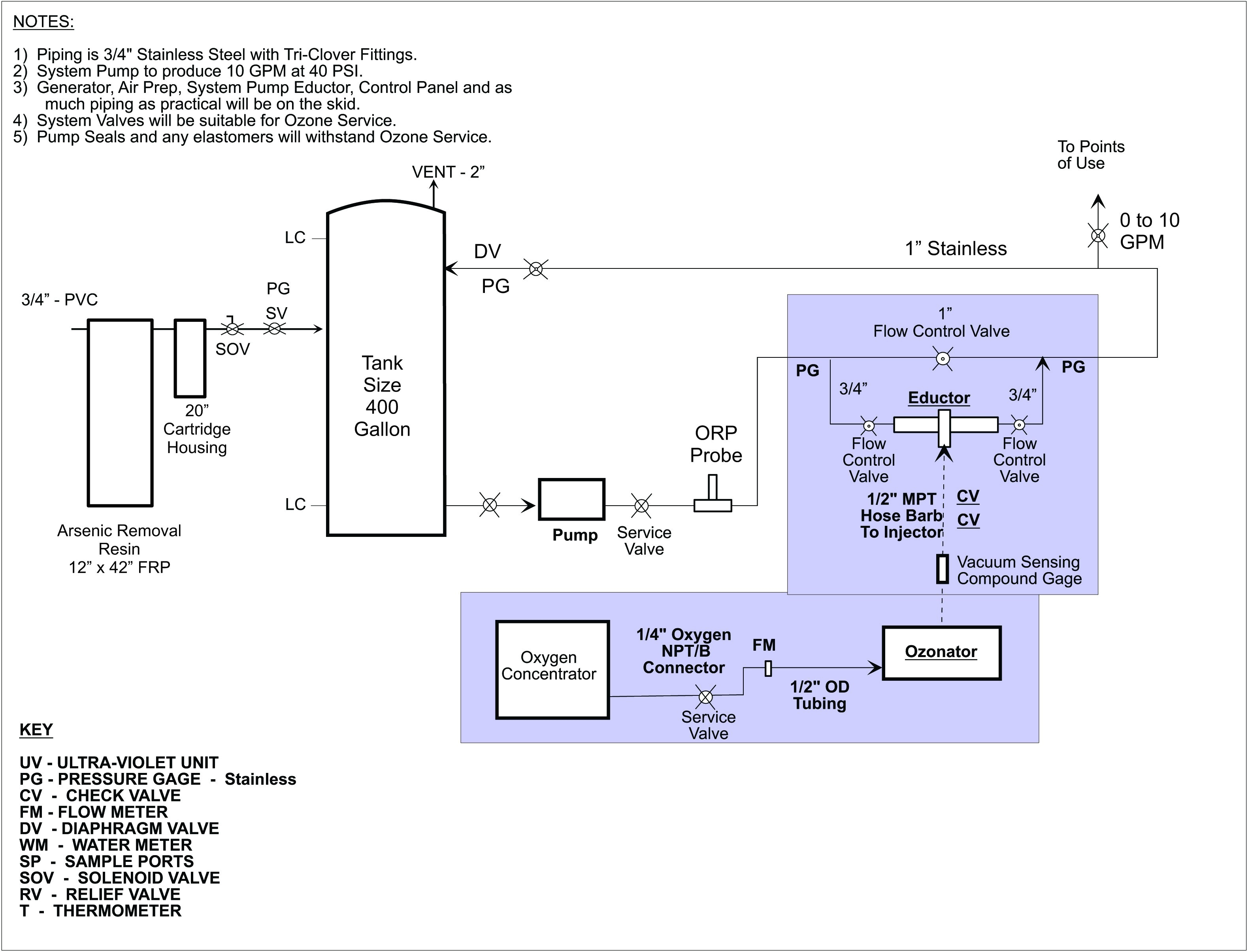
circuit diagram tradeoficcom wiring diagram sys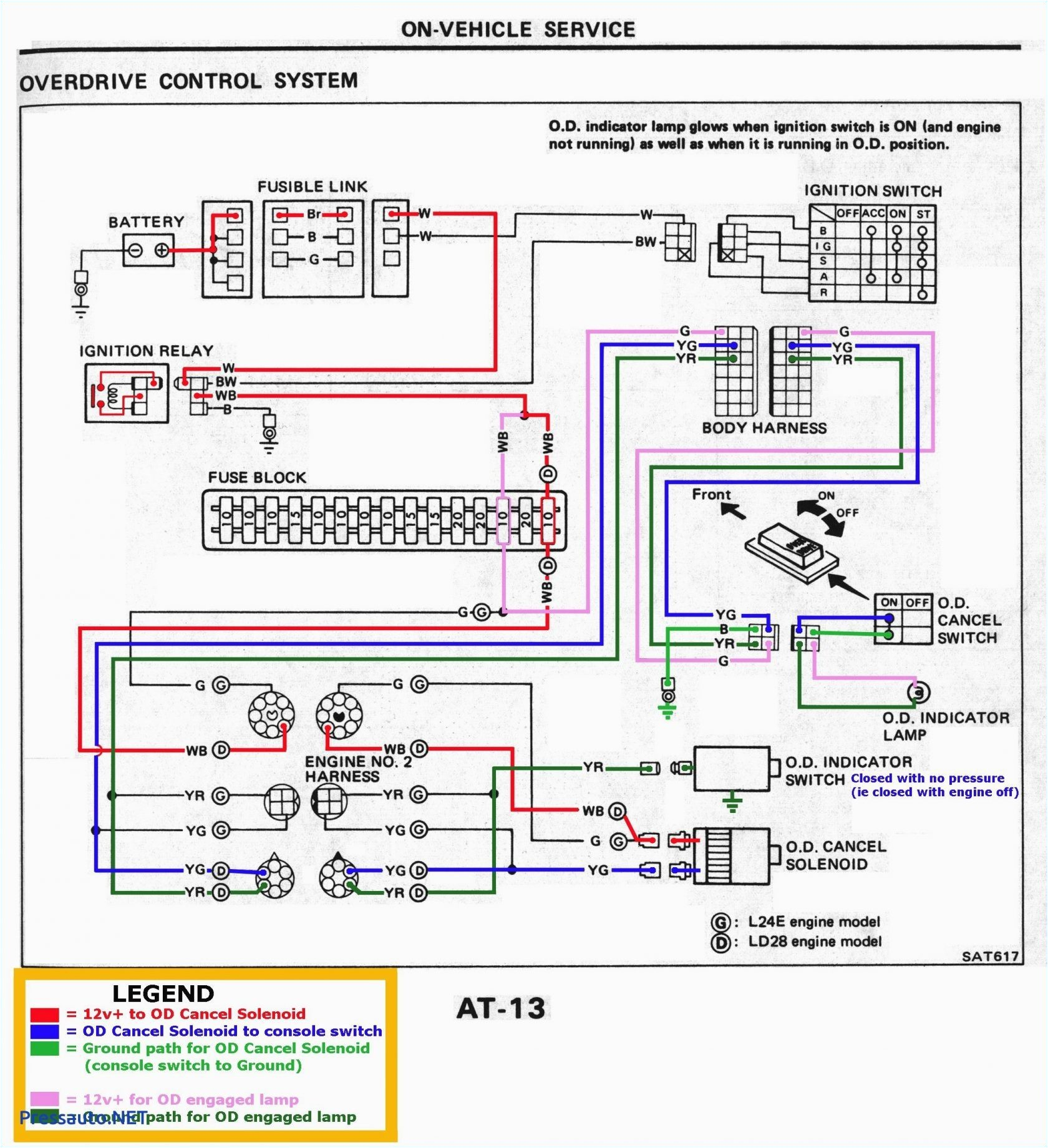
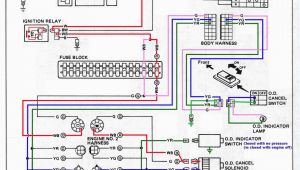
2005 tahoe airbag wiring diagram wiring diagram img
A set of wiring diagrams may be required by the electrical inspection authority to assume link of the dwelling to the public electrical supply system.
Wiring diagrams will in addition to add together panel schedules for circuit breaker panelboards, and riser diagrams for special facilities such as flame alarm or closed circuit television or extra special services.
You Might Also Like :
- 2003 Pontiac Bonneville Wiring Diagram
- 50 Amp Gfci Breaker Wiring Diagram
- 2008 Tahoe Stereo Wiring Diagram
high voltage wiring diagram another image:
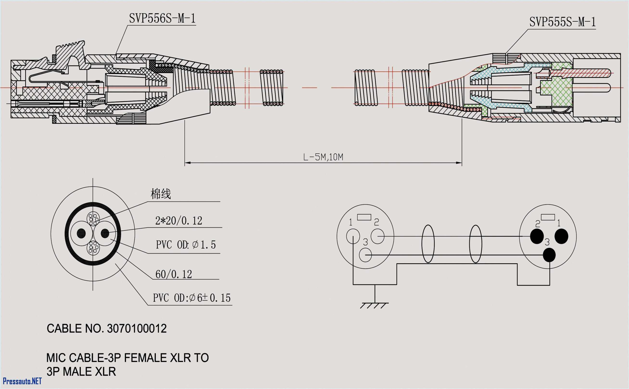
4 prong voltage regulator wiring diagram wiring diagram technic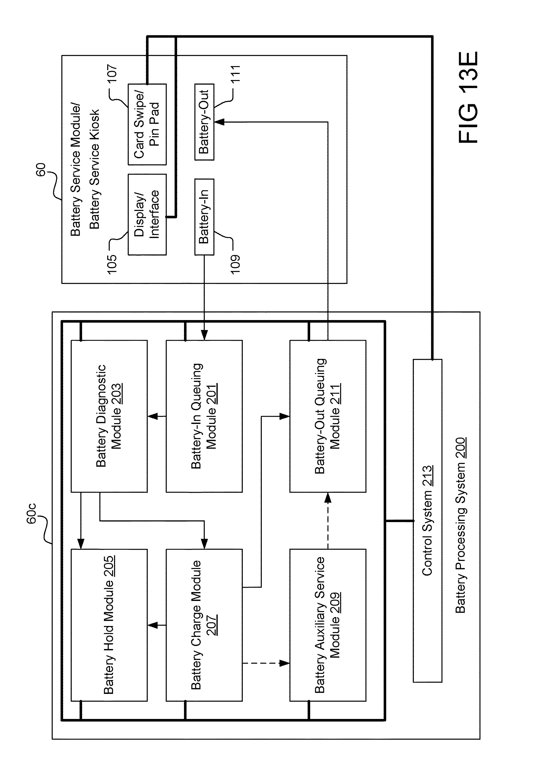
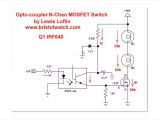
highvoltage supply circuit diagram tradeoficcom wiring diagram rows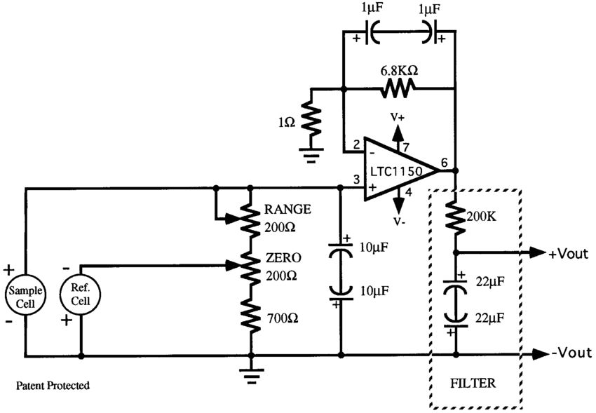
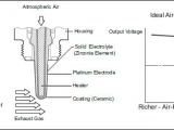
oxygen sensor schematic wiring diagrams value
high voltage wiring diagram wiring diagram chart high voltage wiring diagram high voltage motor wiring diagram wiring auto wiring diagrams three phase wiring diagrams weg electric motors three phase wiring diagrams always use wiring diagram supplied on motor nameplate colored leads are only applicable on the new rolled steel motor lines single phase wiring diagrams always use wiring diagram supplied on motor nameplate for motors with thermal protection single voltage single rotation single voltage reversible rotation dual voltage single rotation split phase motor beautiful of high voltage wiring diagram 2019 high voltage wiring diagram beautiful of high voltage wiring diagram 2019 demi kenyamanan pembaca kita group the beautiful of high voltage wiring diagram 2019 on the labels high voltage wiring diagram motor high voltage wiring diagrams high voltage motor wiring diagram high voltage wiring diagram motor high voltage wiring diagrams high voltage generator schematic circuit diagram this high voltage generator was designed with the aim of testing the electrical breakdown protection used on the railways these protection measures are used to ensure that any external metal parts will never be at a high voltage high voltage wiring diagram wire diagram high voltage wiring diagram allowed to the website in this time i ll show you about high voltage wiring diagram and after this this is actually the very first impression high voltage circuit wiring diagrams 2 different values of d3 can be used to get different output voltages from about 0 6v to around 30v note that at higher voltages the circuit might not perform as well and may not produce as much current you may also need to use a larger c3 for higher voltages and or higher currents 3 you can use a larger value for c3 to provide better filtering 4 the circuit will require about 2a from the 6v supply to provide the full 800ma at 12v high voltage battery wiring module corresponding to 46 high voltage battery wiring module corresponding to changes in number of battery cells automotive 1 introduction in recent years demand has been increasing for high voltage power supply circuit wiring diagrams this high voltage power supply can generate voltage of 5000 volts dc from 230 vac line voltage its main purpose is the production of negative ions charging system wiring diagram charging system wiring diagram amazon printed books https www createspace com 3623931 amazon kindle edition http www amazon com automotive elec ac motor wiring diagram for low high voltage how to wire in the low voltage setup attach p1 to neut t2 t4 t5 to hot and the case to ground there should be a male spade lug attached to the case or a green colored screw in the hi setup p1 to hot t4 t5 to the other hot ground to the case green lug all the middle wires that say tape use a wire nut to join the indicated wires together
