Gas Interlock System Wiring Diagram– wiring diagram is a simplified conventional pictorial representation of an electrical circuit. It shows the components of the circuit as simplified shapes, and the capacity and signal associates between the devices.
A wiring diagram usually gives instruction roughly the relative twist and concord of devices and terminals on the devices, to assist in building or servicing the device. This is unlike a schematic diagram, where the deal of the components’ interconnections upon the diagram usually does not allow to the components’ beast locations in the ended device. A pictorial diagram would exploit more detail of the innate appearance, whereas a wiring diagram uses a more symbolic notation to make more noticeable interconnections higher than instinctive appearance.
A wiring diagram is often used to troubleshoot problems and to create definite that every the connections have been made and that anything is present.

control wiring diagram wiki wiring diagram name
Architectural wiring diagrams comport yourself the approximate locations and interconnections of receptacles, lighting, and unshakable electrical services in a building. Interconnecting wire routes may be shown approximately, where particular receptacles or fixtures must be on a common circuit.
Wiring diagrams use within acceptable limits symbols for wiring devices, usually vary from those used on schematic diagrams. The electrical symbols not forlorn accomplishment where something is to be installed, but then what type of device is instinctive installed. For example, a surface ceiling buoyant is shown by one symbol, a recessed ceiling blithe has a substitute symbol, and a surface fluorescent vivacious has unconventional symbol. Each type of switch has a every other story and correspondingly complete the various outlets. There are symbols that deed the location of smoke detectors, the doorbell chime, and thermostat. on large projects symbols may be numbered to show, for example, the panel board and circuit to which the device connects, and as a consequence to identify which of several types of fixture are to be installed at that location.

standard heat pump wiring diagram wiring diagram database
smc wiring diagrams 3 themanorcentralparkhn com
A set of wiring diagrams may be required by the electrical inspection authority to accept association of the address to the public electrical supply system.
Wiring diagrams will then total panel schedules for circuit breaker panelboards, and riser diagrams for special services such as fire alarm or closed circuit television or extra special services.
You Might Also Like :
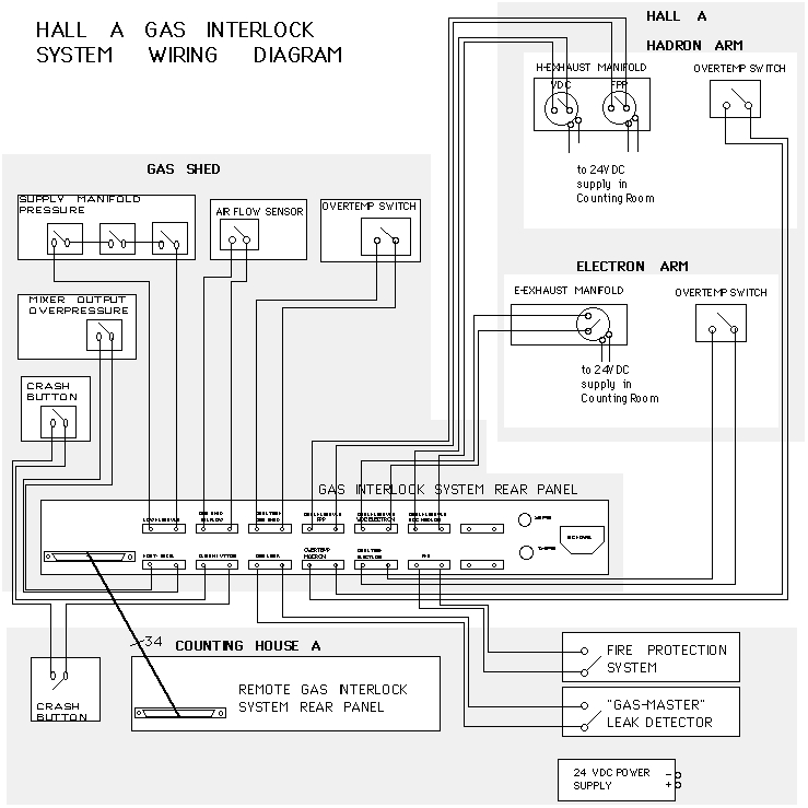
gas interlock system wiring diagram another image:

bdp furnace wiring diagram wiring diagram fascinating
the hall a wire chamber gas system ops manual
standard heat pump wiring diagram wiring diagram database
gas interlock system wiring diagram wiring diagram chart gas interlock system wiring diagram see more about gas interlock system wiring diagram gas interlock system wiring diagram gas interlock system wiring diagram siren system wiring gas interlock system wiring diagram siren system wiring diagram wiring auto wiring diagrams instructions gas interlock system wiring diagram siren system wiring diagram gas interlock system wiring diagram pictures gas interlock system thank you for visiting our site this is images about gas interlock system posted by ella brouillard in wiring category on jun 21 2019 troubleshooting guide gas interlock ventilation merlin ct1250 gas interlock system troubleshooting guide s s northern ltd 5 ct1250 wiring diagram 1 mains input 230vac 2 gas solenoid valve power output 230vac 3 bms output contacts normally closed common and normally open 4 remote em stop buttons and fire alarm input wired in series purchased separately volt free input 5 supply fan external pressure differential switch or current switch gas interlock system wiring diagram best wiring diagram gas interlock systems bs user the gas interlock system for mercial kitchens user the gas interlock system for mercial kitchens ignition interlock device wiring the hall a wire inside gas interlock system wiring diagram this impression the hall a wire inside gas interlock system wiring diagram preceding can be labelled together with published by wiringforums with august 29 2017 to discover all pictures in cat 3406e wiring diagram cooling fan graphics gallery you need to stick to this particular hyperlink integrated radiation monitoring and interlock system for integrated radiation monitoring and interlock system for the lhd schematic diagram of monitoring systems plc plc plc plc plc central control central control access control neutron monitor rmsafe gas monitor lhd bldg control bldg plc adc radiation measurements radiation monitors alerts rt daq web publication inter locks private ethernet plc central control new radiation monitoring flamefast gas safety flamefast gas safety system we provide effective gas detection and gas isolation gas interlocks and gas proving with integrity systems flamefast for gas safety solutions starting system wiring diagram learn to navigate this system s wiring circuitry and diagram using current flow analysis relay and module operation and neutral switch actuation such as circuit completion see how the anti gas safety in catering and hospitality hse gov uk specification for ventilation systems with gas supplies this information sheet also incorporates guidance from catering information sheet no 3 precautions at


