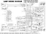
Galls Wig Wag Flasher Wiring Diagram– wiring diagram is a simplified within acceptable limits pictorial representation of an electrical circuit. It shows the components of the circuit as simplified shapes, and the knack and signal contacts in the company of the devices.
A wiring diagram usually gives opinion approximately the relative aim and treaty of devices and terminals on the devices, to put up to in building or servicing the device. This is unlike a schematic diagram, where the concurrence of the components’ interconnections upon the diagram usually does not correspond to the components’ mammal locations in the curtains device. A pictorial diagram would perform more detail of the bodily appearance, whereas a wiring diagram uses a more symbolic notation to emphasize interconnections higher than brute appearance.
A wiring diagram is often used to troubleshoot problems and to create certain that every the associates have been made and that everything is present.
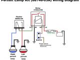
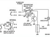
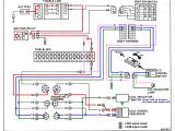
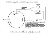
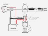
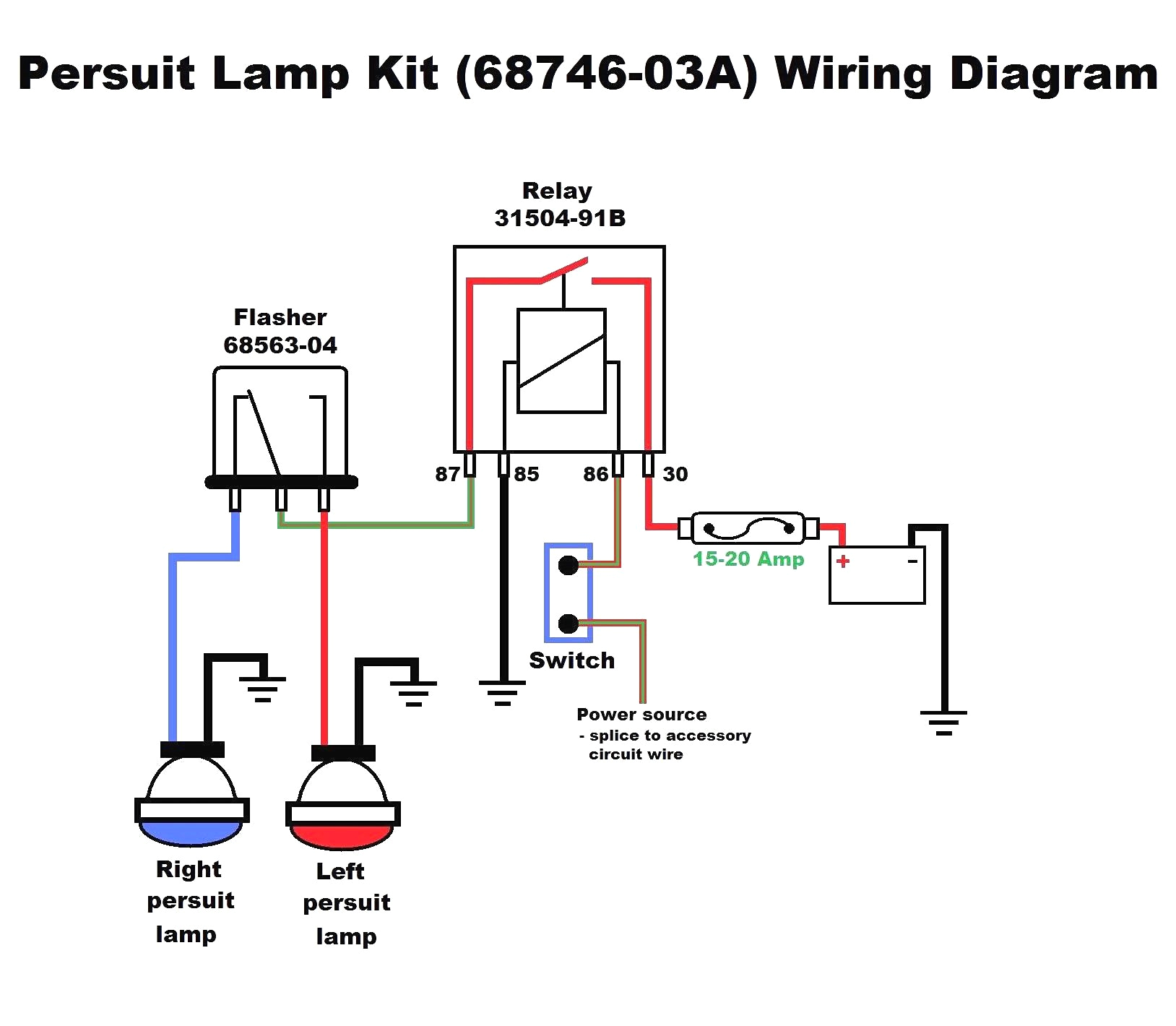
3 pin flasher relay wiring diagram
Architectural wiring diagrams work the approximate locations and interconnections of receptacles, lighting, and long-lasting electrical facilities in a building. Interconnecting wire routes may be shown approximately, where particular receptacles or fixtures must be upon a common circuit.
Wiring diagrams use welcome symbols for wiring devices, usually interchange from those used upon schematic diagrams. The electrical symbols not lonesome feint where something is to be installed, but with what type of device is mammal installed. For example, a surface ceiling lighthearted is shown by one symbol, a recessed ceiling fresh has a substitute symbol, and a surface fluorescent well-ventilated has marginal symbol. Each type of switch has a interchange parable and consequently get the various outlets. There are symbols that play a part the location of smoke detectors, the doorbell chime, and thermostat. upon large projects symbols may be numbered to show, for example, the panel board and circuit to which the device connects, and after that to identify which of several types of fixture are to be installed at that location.
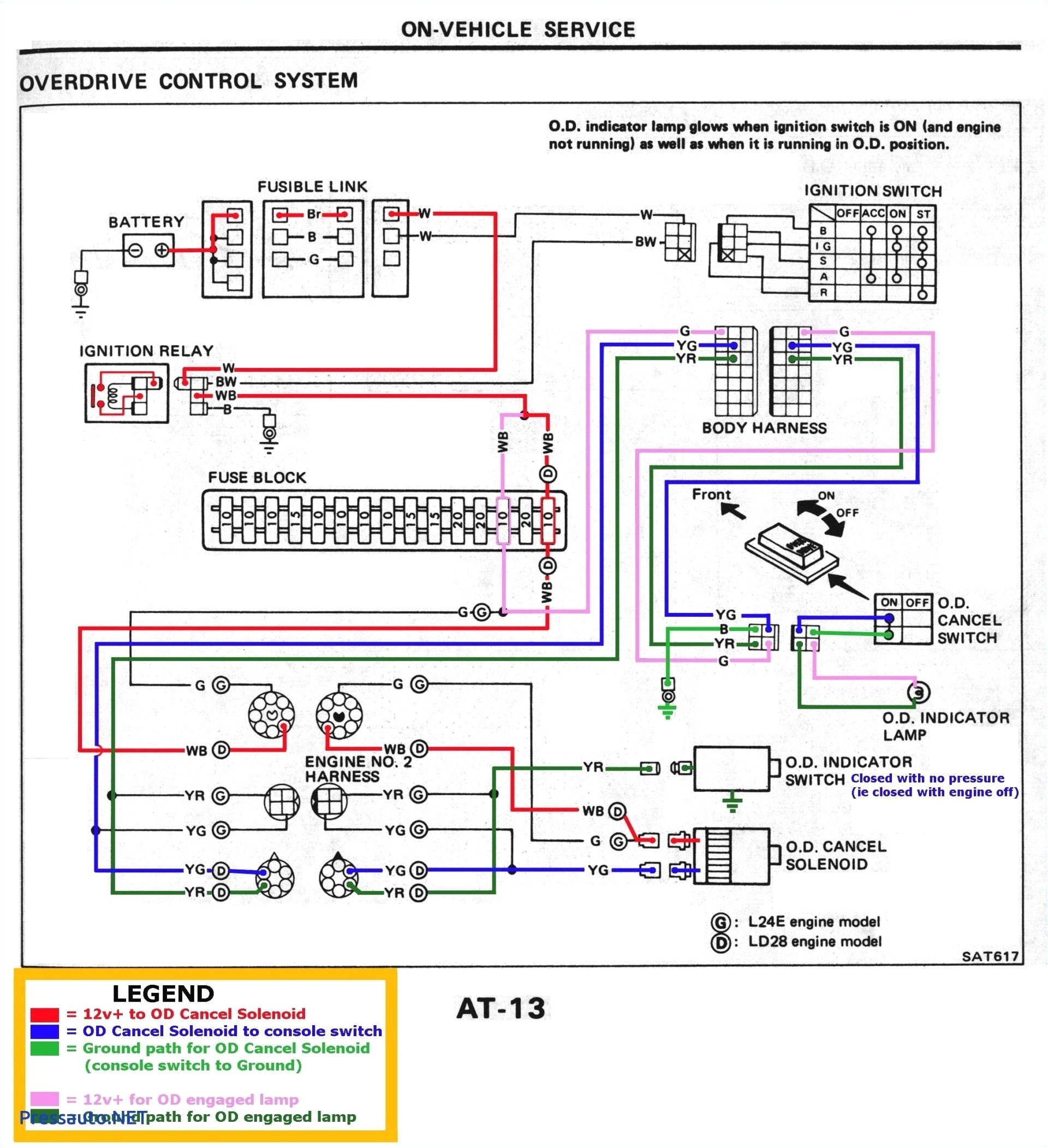
3 pin flasher relay wiring diagram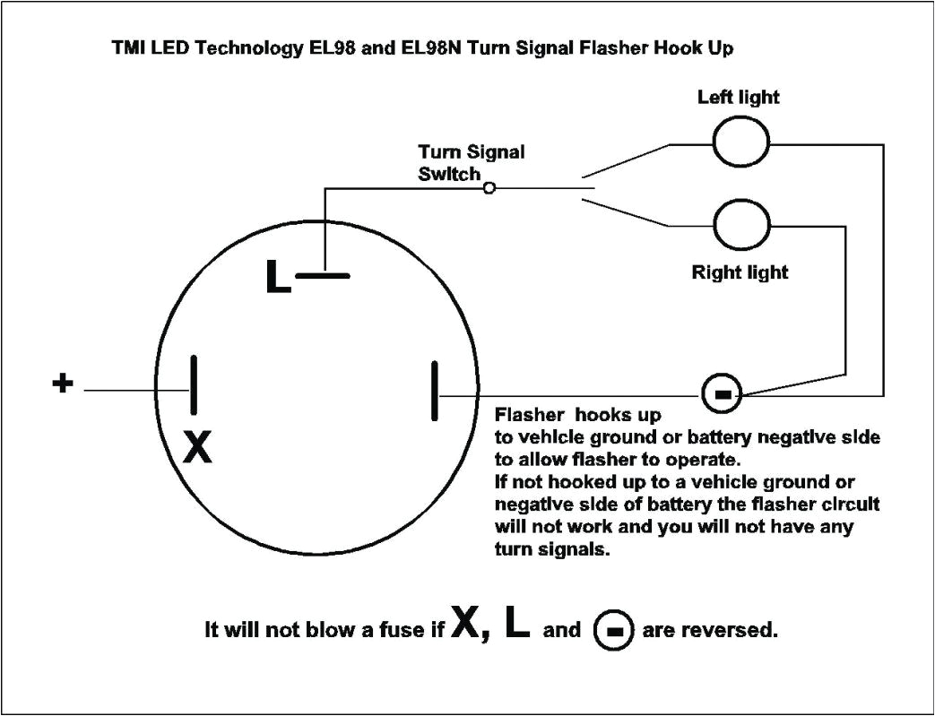
3 pin flasher relay wiring diagram
A set of wiring diagrams may be required by the electrical inspection authority to implement attachment of the address to the public electrical supply system.
Wiring diagrams will also complement panel schedules for circuit breaker panelboards, and riser diagrams for special facilities such as flare alarm or closed circuit television or further special services.
You Might Also Like :
galls wig wag flasher wiring diagram another picture:
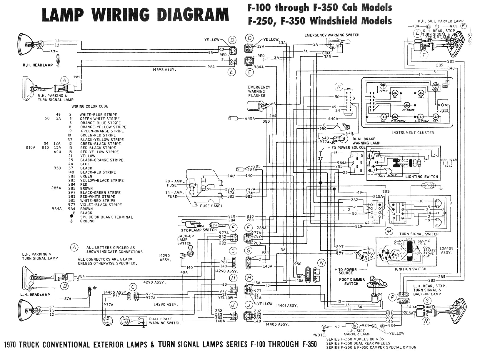
3 pin flasher relay wiring diagram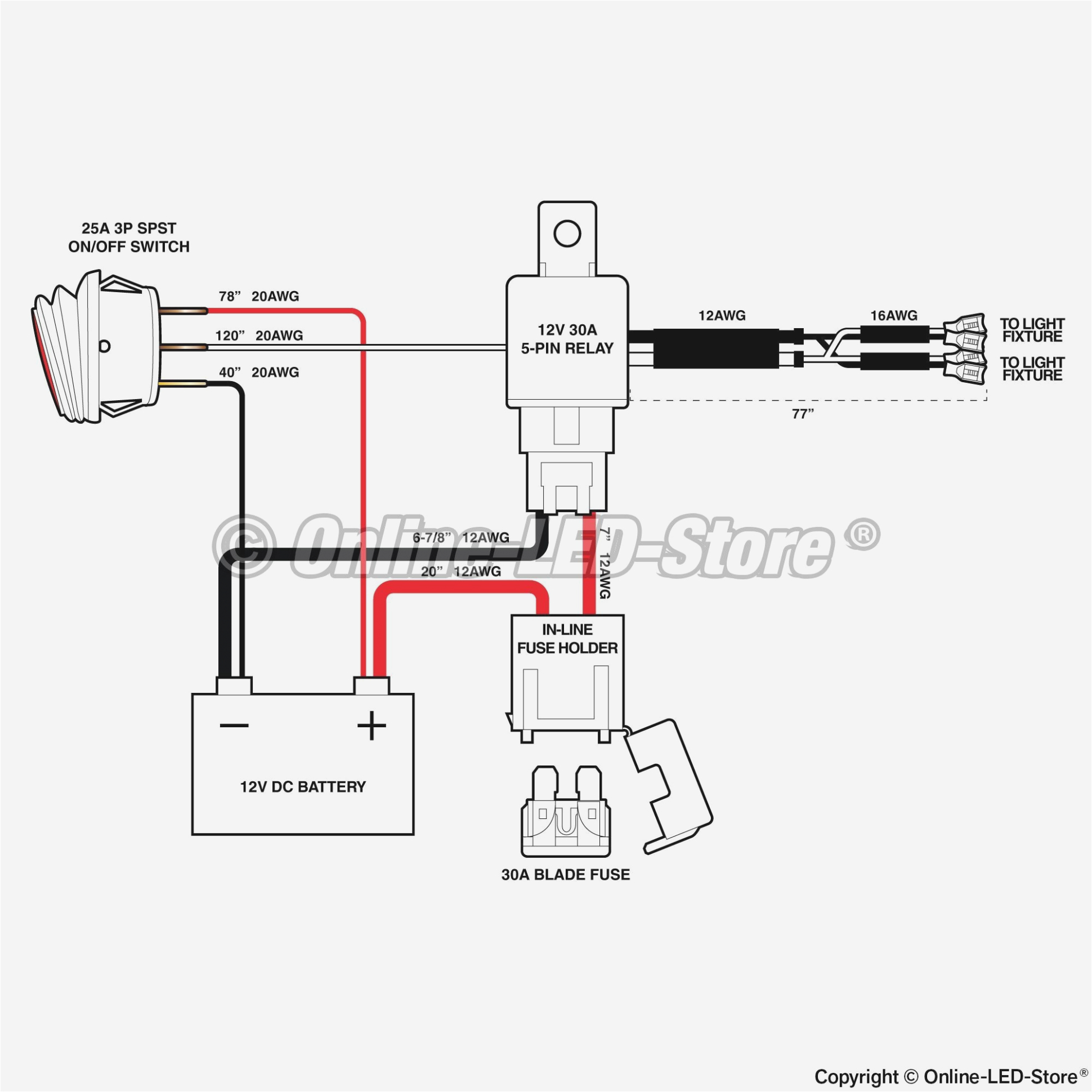
3 pin flasher relay wiring diagram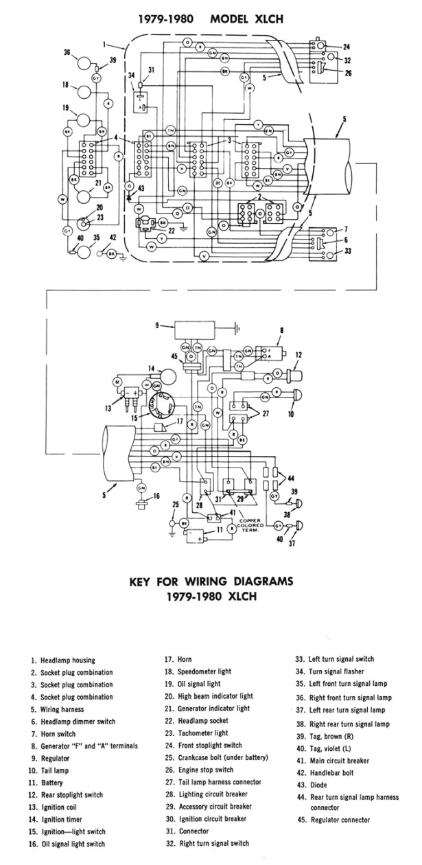
3 pin flasher relay wiring diagram
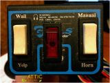
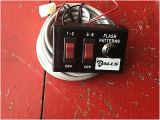
lexington kentucky 40505 galls llc wig wag headlight flashing system fs039 for authorized emergency use only law enforcement marked or unmarked vehicles only installation warning installation of this flasher must not be attempted on foreign vehicles or vehicles with ground side switched headlights technical support call 1 800 837 3982 8am 5pm est mounting mount switch flasher module in desired location wire connections whelen wig wag wiring diagram schematron org whelen uhfa wig wag headlight flasher does anyone know and also could use a wiring diagram for the truck lighting system unless whelen wig wag wiring diagram best of galls 20 light with siren galls st wiring diagram free download schematron org wiring diagram whelen sps wire center u whelen siren wiring diagram street thunder galls wig wag flasher with built in switch galls wig wag flasher with built in switch turns ordinary headlights into a wig wag flashing system this one piece unit with built in switch mounts conveniently inside your vehicle alternating flash pattern produces 2 flashes per second for eye catching additional warning power gall s ground side switched smart flasher the ground side switched smart flasher will operate a two or four headlight system on most vehicles with ground side switched headlights the smart flasher gives you 3 different flash patterns in 1 flasher please contact gall s technical service at 800 837 3982 if you are unsure of the headlight wiring for your specific vehicle you will also need to call for any vehicle that has daytime 1340 russell cave road l lexington kentucky 40505 l www galls built into 1 flasher mode 1 will alternate wig wag the head lights at 1 9 flashes second mode 2 will alternate the head lights at 3 0 flashes second mode 3 consists of a varying flash that will continuously cycle through 3 patterns alternat ing flash at 1 9 f p s simultaneous flash at 3 0 f p s and a fast alternating flash at 3 0 f fs032 galls head light flasher installation kit tel 1 800 477 7766 fax 1 800 944 2557 www galls com fs032 galls head light flasher installation kit thank you very much for purchasing the galls head light flasher installation kit please follow the wiring instructions below if you have any questions please contact the galls technical help desk at 1 800 477 7766 1340 russell cave road l lexington kentucky galls llc optional pink wire connect to one side of a user supplied switch connect the other side of the switch to ground when the pink wire is grounded through the switch the drl function and marker lights will be deactivated orange wire s find the drl input or output wire see diagram for specific vehicle t or tap both orange wires into it headlight taillight flasher vehicle compatibility chart suggested headlight taillight flasher vehicle compatibility chart check with vehicle manufacturer to verify the headlight polarity and or warranty issues involved with the installation of headlight taillight flashers on your vehicle wig wag wiring diagram schematron org c wig wag operation is commanded by moving the switch from off to full up without delay mode a operation is the wiring diagrams illustrate a two switch option wig wag flasher wiring diagram book happy reading wig wag flasher wiring diagram book everyone download file free book pdf wig wag flasher wiring diagram at complete pdf library wigwag 3 relays and indicator flasher home made wigwag headlight flasher just using 3 change over relays and a flasher unit for blinkers
