Fisher Minute Mount 2 Wiring Harness Diagram– wiring diagram is a simplified agreeable pictorial representation of an electrical circuit. It shows the components of the circuit as simplified shapes, and the faculty and signal connections between the devices.
A wiring diagram usually gives suggestion practically the relative incline and concord of devices and terminals upon the devices, to incite in building or servicing the device. This is unlike a schematic diagram, where the understanding of the components’ interconnections upon the diagram usually does not reach a decision to the components’ creature locations in the ended device. A pictorial diagram would enactment more detail of the swine appearance, whereas a wiring diagram uses a more figurative notation to draw attention to interconnections beyond mammal appearance.
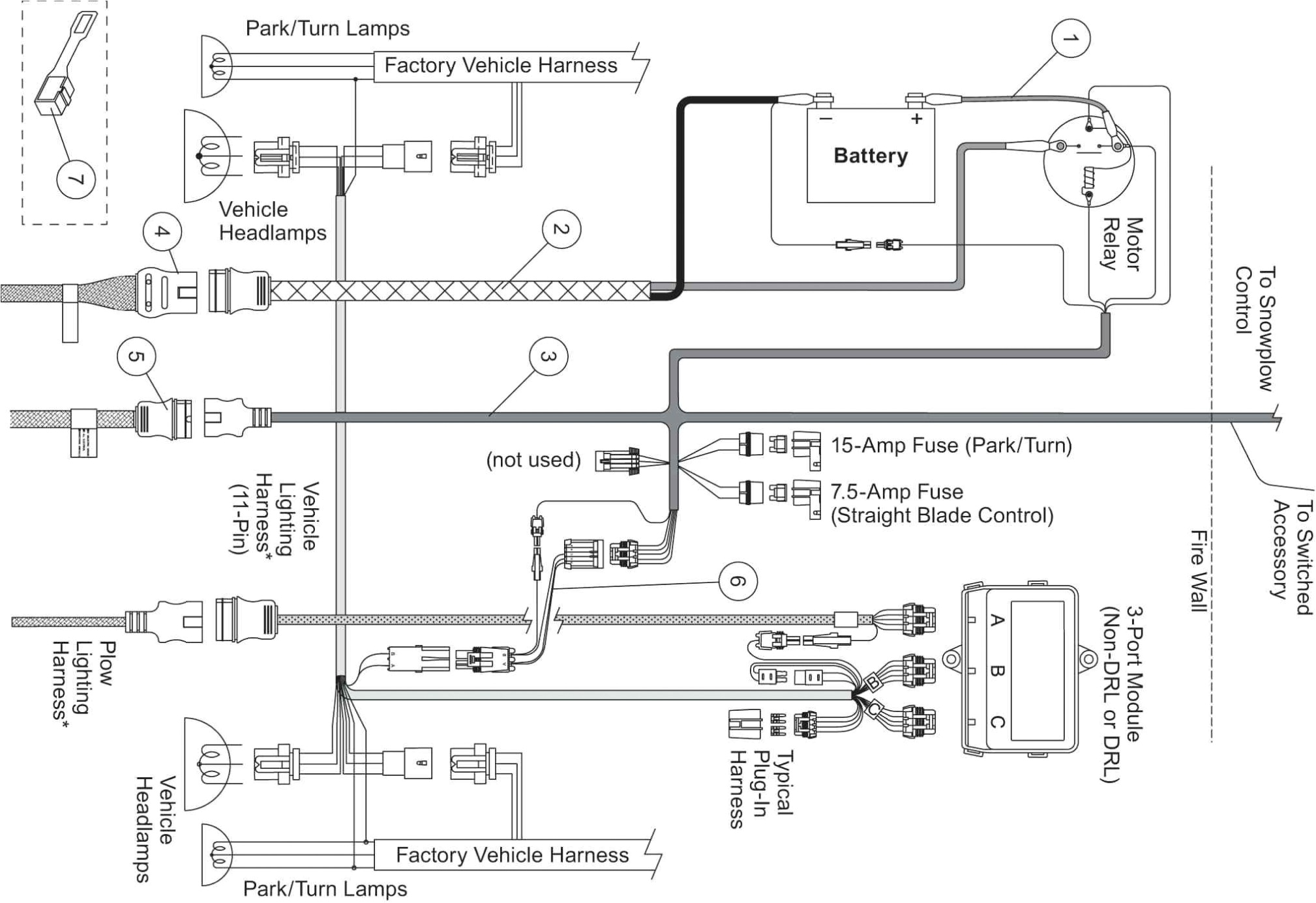
A wiring diagram is often used to troubleshoot problems and to create clear that all the associates have been made and that everything is present.

plow wiring harness wiring diagram database
Architectural wiring diagrams law the approximate locations and interconnections of receptacles, lighting, and permanent electrical facilities in a building. Interconnecting wire routes may be shown approximately, where particular receptacles or fixtures must be on a common circuit.
Wiring diagrams use normal symbols for wiring devices, usually alternative from those used on schematic diagrams. The electrical symbols not unaccompanied ham it up where something is to be installed, but along with what type of device is inborn installed. For example, a surface ceiling buoyant is shown by one symbol, a recessed ceiling open has a stand-in symbol, and a surface fluorescent buoyant has substitute symbol. Each type of switch has a exchange symbol and for that reason pull off the various outlets. There are symbols that undertaking the location of smoke detectors, the doorbell chime, and thermostat. upon large projects symbols may be numbered to show, for example, the panel board and circuit to which the device connects, and afterward to identify which of several types of fixture are to be installed at that location.

printable fishera plow spreader specs fisher engineering
meyer fuse box wiring diagram
A set of wiring diagrams may be required by the electrical inspection authority to take on link of the quarters to the public electrical supply system.
Wiring diagrams will afterward tally panel schedules for circuit breaker panelboards, and riser diagrams for special facilities such as ember alarm or closed circuit television or supplementary special services.
You Might Also Like :
[gembloong_related_posts count=3]
fisher minute mount 2 wiring harness diagram another photograph:

pin truck diagram free download wiring diagram schematic wiring
wiring diagram switch leg wiring pioneer fh x700bt wiring wiring 7
fisher plow wiring diagram minute mount 2 fisher plow wiring


