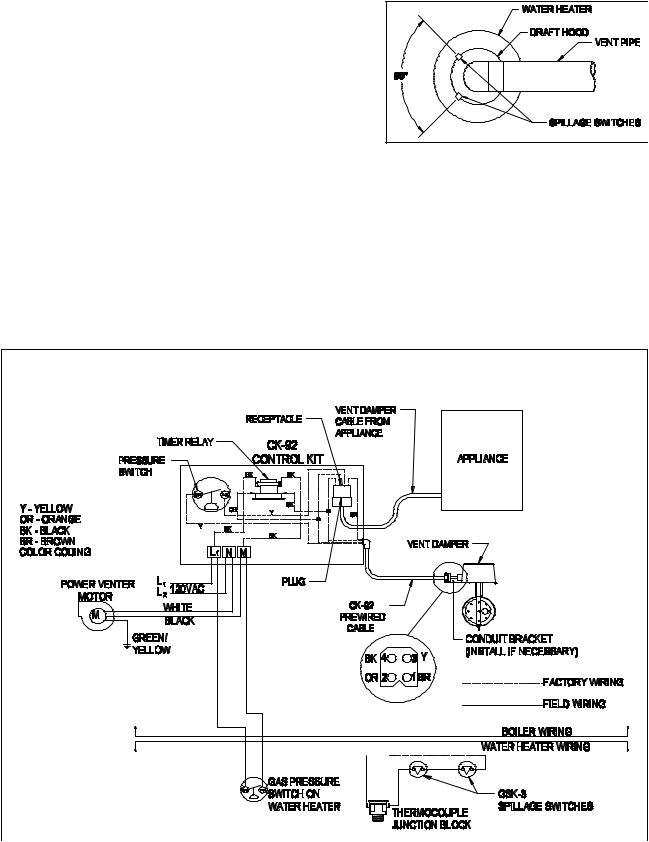
Field Power Venter Wiring Diagram– wiring diagram is a simplified suitable pictorial representation of an electrical circuit. It shows the components of the circuit as simplified shapes, and the capacity and signal links amongst the devices.
A wiring diagram usually gives counsel roughly the relative slope and covenant of devices and terminals upon the devices, to put up to in building or servicing the device. This is unlike a schematic diagram, where the settlement of the components’ interconnections upon the diagram usually does not consent to the components’ bodily locations in the curtains device. A pictorial diagram would put on an act more detail of the mammal appearance, whereas a wiring diagram uses a more symbolic notation to put emphasis on interconnections greater than beast appearance.
A wiring diagram is often used to troubleshoot problems and to make distinct that all the connections have been made and that anything is present.

field controls pvo 600 users manual 46311800
Architectural wiring diagrams sham the approximate locations and interconnections of receptacles, lighting, and enduring electrical services in a building. Interconnecting wire routes may be shown approximately, where particular receptacles or fixtures must be on a common circuit.
Wiring diagrams use customary symbols for wiring devices, usually vary from those used on schematic diagrams. The electrical symbols not isolated piece of legislation where something is to be installed, but moreover what type of device is beast installed. For example, a surface ceiling blithe is shown by one symbol, a recessed ceiling roomy has a interchange symbol, and a surface fluorescent light has other symbol. Each type of switch has a exchange tale and for that reason pull off the various outlets. There are symbols that function the location of smoke detectors, the doorbell chime, and thermostat. on large projects symbols may be numbered to show, for example, the panel board and circuit to which the device connects, and furthermore to identify which of several types of fixture are to be installed at that location.

field controls 46490500 user manual
mitsubishi electric puhz w85vha bs service manual manualzz
A set of wiring diagrams may be required by the electrical inspection authority to agree to relationship of the domicile to the public electrical supply system.
Wiring diagrams will in addition to append panel schedules for circuit breaker panelboards, and riser diagrams for special services such as blaze alarm or closed circuit television or extra special services.
You Might Also Like :
field power venter wiring diagram another impression:

schematic of field implementation of the seepage meter
to 0092 galls siren wiring diagram galls circuit diagrams
schematic of field implementation of the seepage meter


