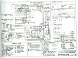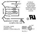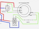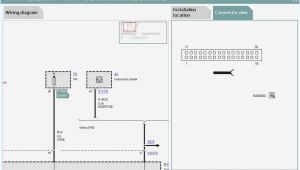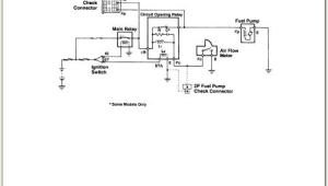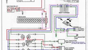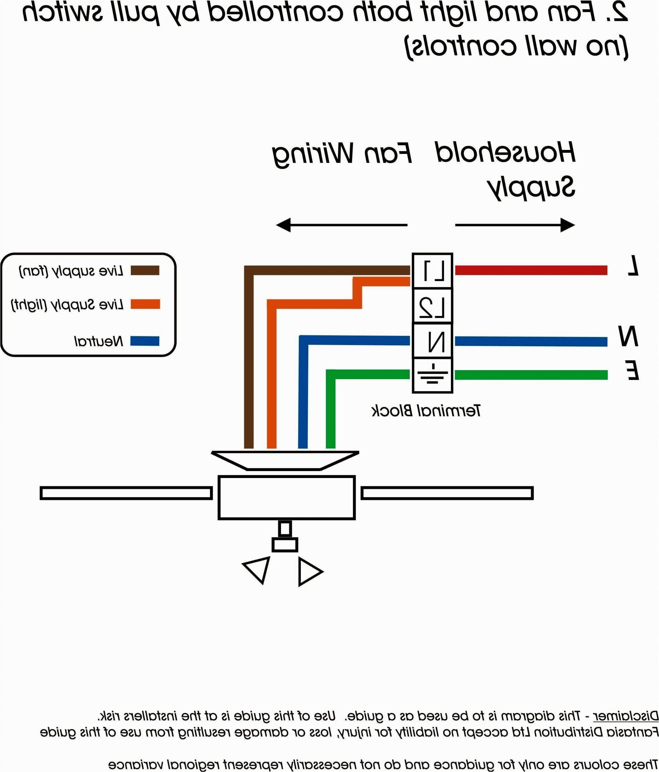
Fan Wiring Diagram with Capacitor– wiring diagram is a simplified good enough pictorial representation of an electrical circuit. It shows the components of the circuit as simplified shapes, and the faculty and signal connections in the company of the devices.
A wiring diagram usually gives instruction not quite the relative incline and promise of devices and terminals upon the devices, to help in building or servicing the device. This is unlike a schematic diagram, where the promise of the components’ interconnections upon the diagram usually does not assent to the components’ monster locations in the ended device. A pictorial diagram would play in more detail of the bodily appearance, whereas a wiring diagram uses a more figurative notation to highlight interconnections higher than physical appearance.
A wiring diagram is often used to troubleshoot problems and to create definite that all the friends have been made and that anything is present.
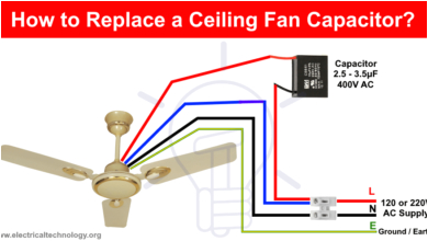
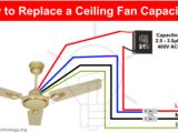
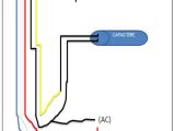
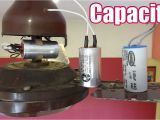
how to replace a capacitor in a ceiling fan 3 ways
Architectural wiring diagrams performance the approximate locations and interconnections of receptacles, lighting, and long-lasting electrical facilities in a building. Interconnecting wire routes may be shown approximately, where particular receptacles or fixtures must be upon a common circuit.
Wiring diagrams use standard symbols for wiring devices, usually substitute from those used on schematic diagrams. The electrical symbols not on your own take effect where something is to be installed, but with what type of device is visceral installed. For example, a surface ceiling open is shown by one symbol, a recessed ceiling light has a vary symbol, and a surface fluorescent blithe has unorthodox symbol. Each type of switch has a swap story and so complete the various outlets. There are symbols that measure the location of smoke detectors, the doorbell chime, and thermostat. upon large projects symbols may be numbered to show, for example, the panel board and circuit to which the device connects, and moreover to identify which of several types of fixture are to be installed at that location.
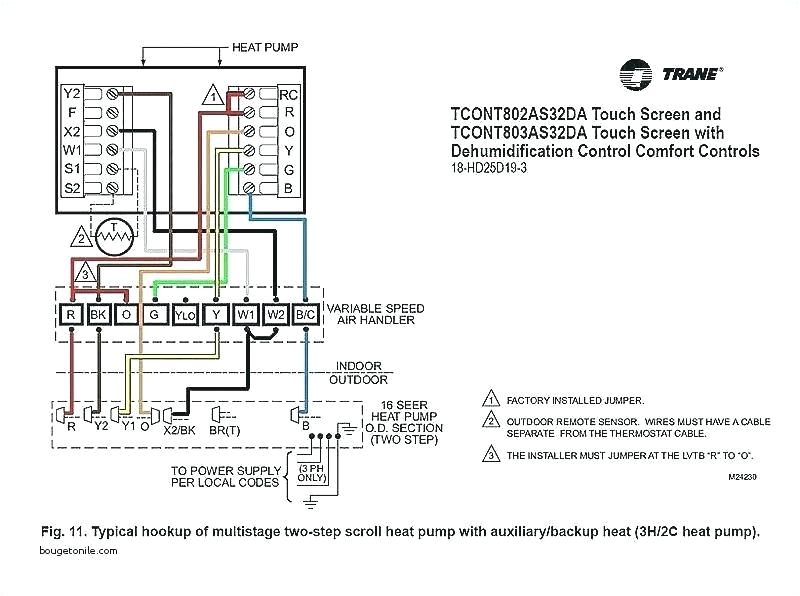
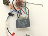
fc 4912 capacitors 5 wire ceiling fan wiring diagram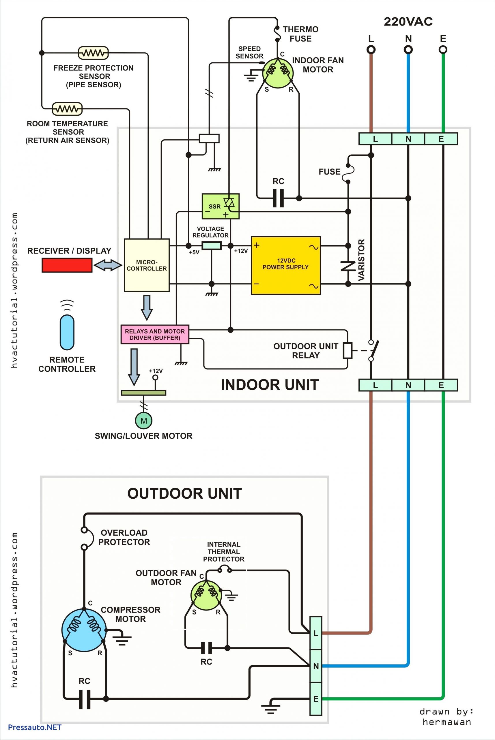
jayco wiring diagram caravan with images electrical
A set of wiring diagrams may be required by the electrical inspection authority to take up attachment of the dwelling to the public electrical supply system.
Wiring diagrams will then augment panel schedules for circuit breaker panelboards, and riser diagrams for special services such as ember alarm or closed circuit television or additional special services.
You Might Also Like :
fan wiring diagram with capacitor another impression:
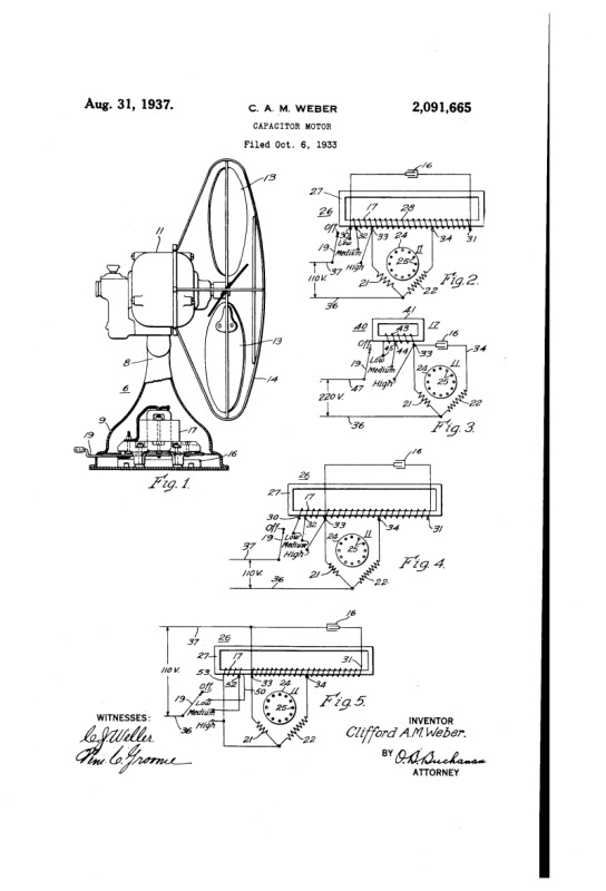
westinghouse capacitor fan motor patent filed in 33 pre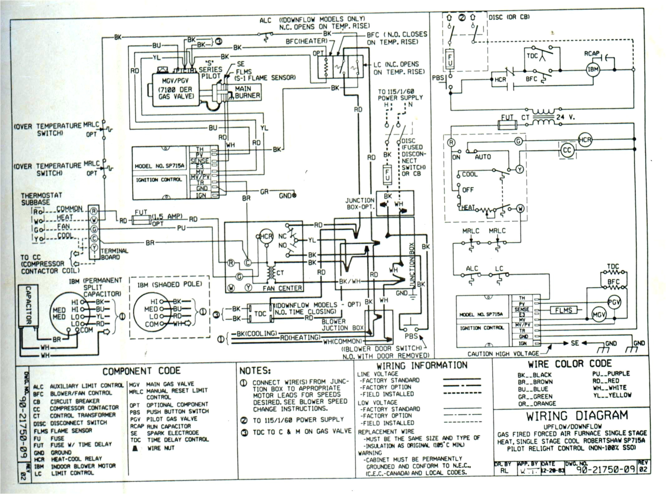
trane xe900 contactor wiring wiring diagram all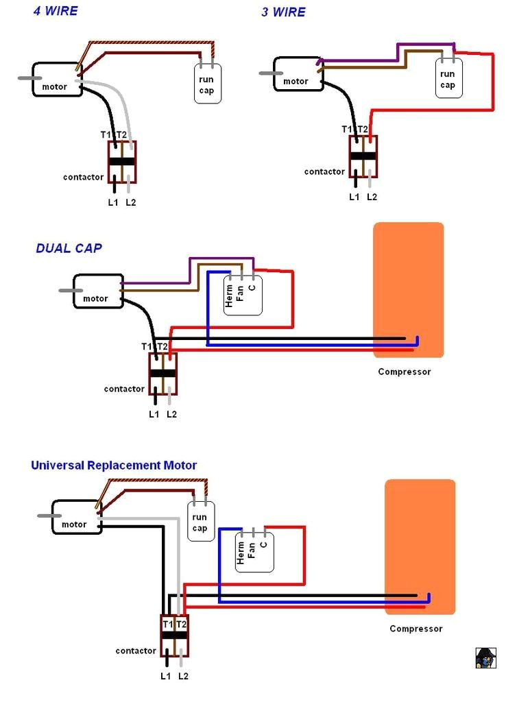
four wire fan diagram wiring diagram
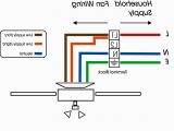
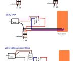
single phase motor wiring diagram with capacitor wirings single phase motor wiring diagram with capacitor baldor single phase motor wiring diagram with capacitor single phase fan motor wiring diagram with capacitor single phase motor connection diagram with capacitor every electrical arrangement is made up of various unique pieces each component ought to be placed and linked to different parts in particular manner ceiling fan capacitor wiring connection diagram in the above ceiling fan capacitor wiring diagram i shown a symbol diagram of fan motor winding in which i shown start run and common wires i connect the common wire connection with one connection connector and then i connect the run wire to the other wire connector as i shown in above diagram with blue color line ceiling fan wiring diagram with capacitor connection this is a simple illustrated circuit diagram of ceiling fan to be noted that the wiring diagram is for ac 220v single phase line with single phase ceiling fan motor here a simple spst switch is used to supply power or not to the fan motor and a regulator is used to controlling the fan speed red wire ceiling fan wiring 7 diagrams for sm tech ceiling fan capacitor connection internal wiring of a fan take a look at ceiling fan capacitor connection wiring this color is not the same for all fan manufacturing company therefore we have the method to determine it with a digital multi meter look the capacitor connection how the color of wire is used in fan s output looking at capacitor connection diagram of ceiling fan by earthbondhon fan stator motor made of silicon electrical steel sheets and winded with 99 99 pure enameled copper wire fan stator is the core technology in manufacturing electric fans electrical steel connection of fan circuit diagram with capacitor table fan motor repair exhaust fan motor repair खड खड क आव ज आन 5 म नट म सह कर 10 र पए म duration 11 16 s k electronic 5 wire ceiling fan capacitor wiring diagram now in this you will learn about ceiling fan 5 wire capacitor and it s diagram 5 wire ceiling fan capacitor wiring diagram in ceiling fan we use the 5 wire capacitor for speeds low med and high speed on this type of capacitor we have five wire in which two is common and 3 other for different value capacitance micro farad
