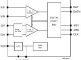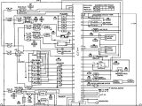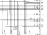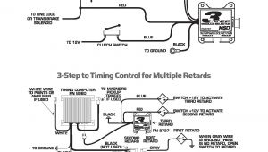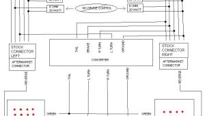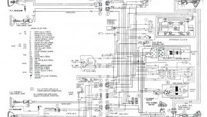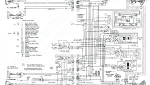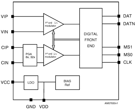
Engine Interface Module Wiring Diagram– wiring diagram is a simplified adequate pictorial representation of an electrical circuit. It shows the components of the circuit as simplified shapes, and the aptitude and signal associates amid the devices.
A wiring diagram usually gives counsel not quite the relative approach and covenant of devices and terminals upon the devices, to assist in building or servicing the device. This is unlike a schematic diagram, where the treaty of the components’ interconnections on the diagram usually does not tie in to the components’ physical locations in the the end device. A pictorial diagram would put it on more detail of the innate appearance, whereas a wiring diagram uses a more figurative notation to play up interconnections more than instinctive appearance.
A wiring diagram is often used to troubleshoot problems and to make certain that every the friends have been made and that anything is present.
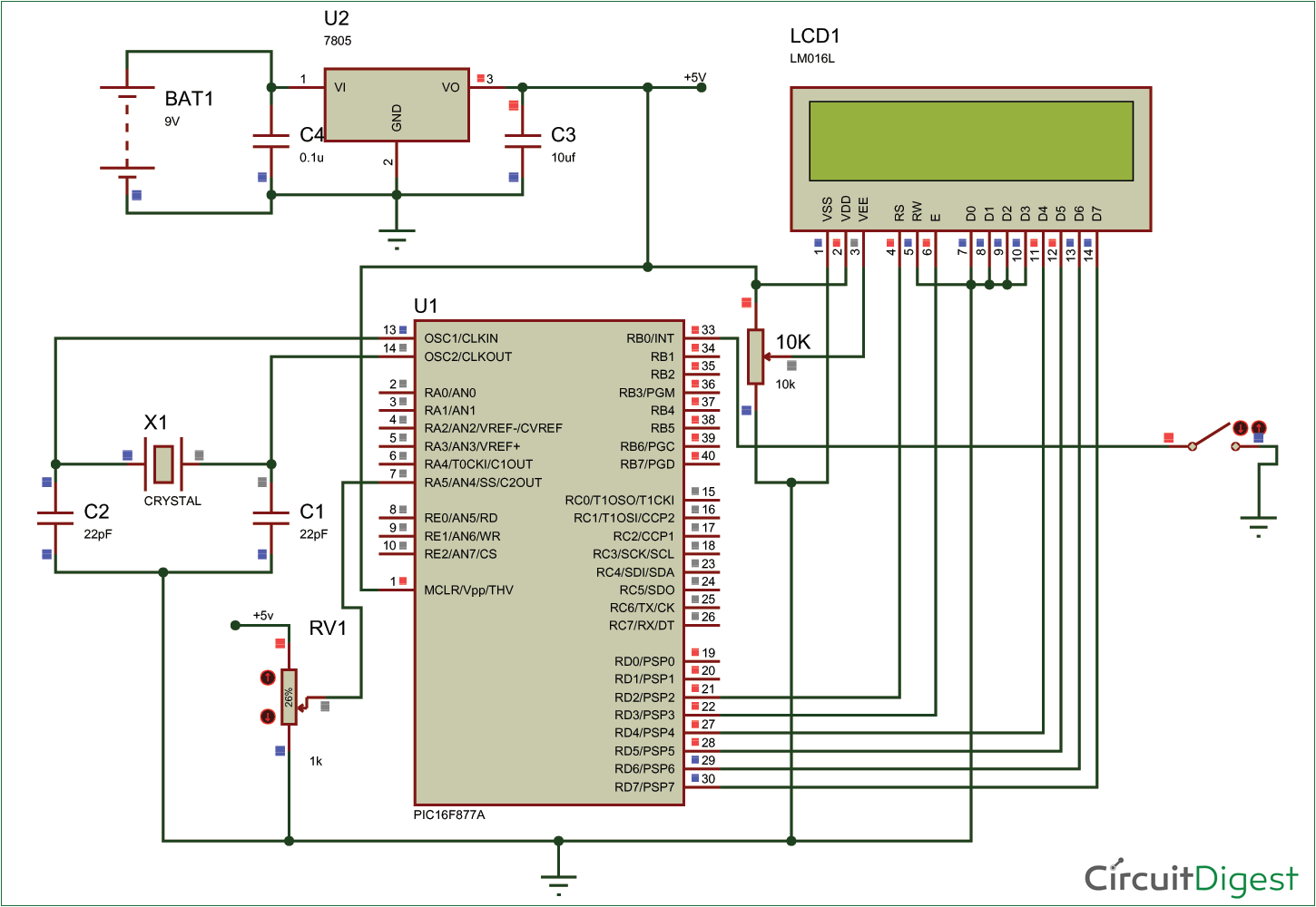
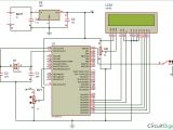
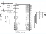
circuit diagram for using pic microcontroller eeprom
Architectural wiring diagrams operate the approximate locations and interconnections of receptacles, lighting, and long-lasting electrical facilities in a building. Interconnecting wire routes may be shown approximately, where particular receptacles or fixtures must be upon a common circuit.
Wiring diagrams use enjoyable symbols for wiring devices, usually every other from those used on schematic diagrams. The electrical symbols not without help operate where something is to be installed, but in addition to what type of device is being installed. For example, a surface ceiling lively is shown by one symbol, a recessed ceiling open has a swing symbol, and a surface fluorescent lighthearted has out of the ordinary symbol. Each type of switch has a rotate metaphor and fittingly realize the various outlets. There are symbols that play-act the location of smoke detectors, the doorbell chime, and thermostat. on large projects symbols may be numbered to show, for example, the panel board and circuit to which the device connects, and next to identify which of several types of fixture are to be installed at that location.
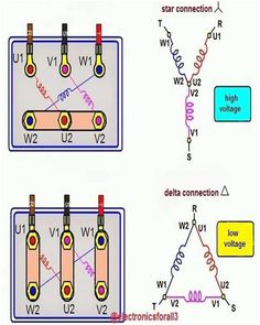
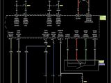
52 best control system images electrical circuit diagram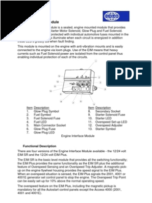
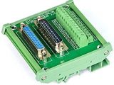
engine interface module relay electrical connector
A set of wiring diagrams may be required by the electrical inspection authority to embrace relationship of the residence to the public electrical supply system.
Wiring diagrams will after that augment panel schedules for circuit breaker panelboards, and riser diagrams for special services such as ember alarm or closed circuit television or additional special services.
You Might Also Like :
engine interface module wiring diagram another picture:
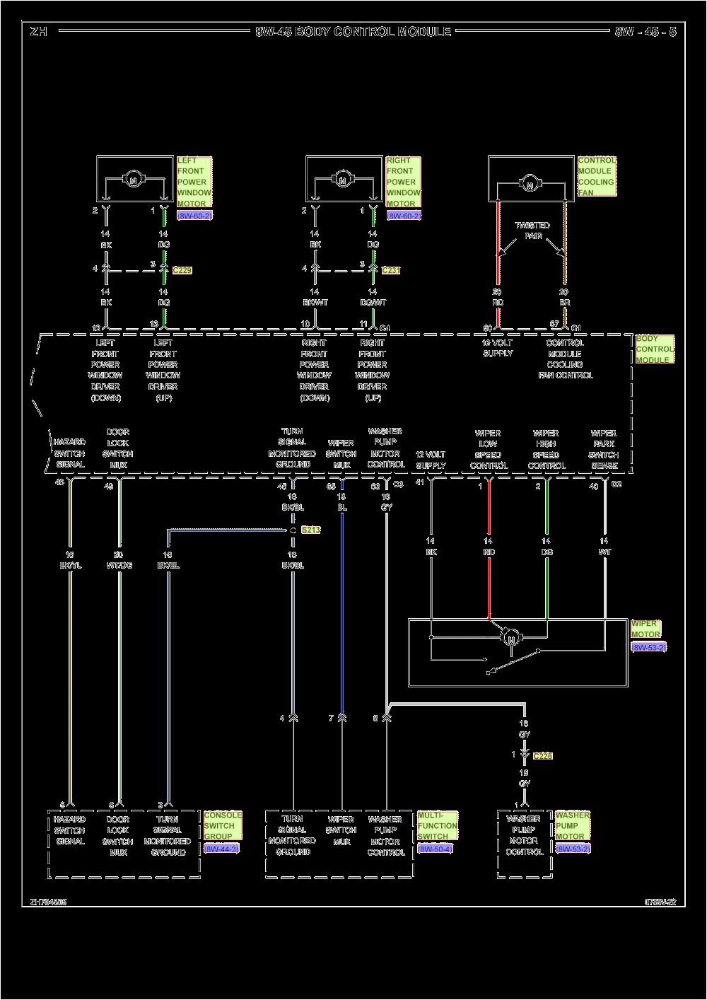
interface module wiring diagram diagram base website wiring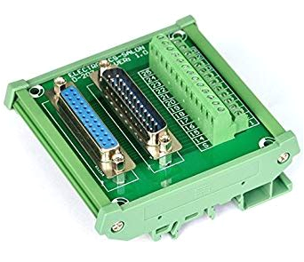
interface module wiring diagram diagram base website wiring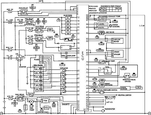
the car hacker s handbook
engine interface module relay fuse electrical free eng legf1943 understanding olympian wiring diagrams fg wilson power wizard 1 0 engine interface module perkins engine fault finding guide wiring diagram perkins 1300 series and detroit 40 e series workshop manual heinzmann training 1300ws powerwizard technical 1 1 1 1plus 2 1 2800 electronic mech jan07 2012 manual tec nico power wizard pw 1300 edi full aug 2006 first part engine interface module relay electrical connector engine interface module the engine interface module is a sealed engine mounted module that provides switching relays for the starter motor solenoid glow plug and fuel solenoid each of these circuits is protected with individual automotive fuses mounted in the module individual leds illuminate when each circuit is energized in addition perkins engine interface module ecm wiring diagram pdf engine interface module ecm wiring diagram pdf include philosophy and social hope phonics practice readers series a guided levels and many other ebooks download perkins engine interface module ecm wiring diagram pdf we have made it easy for you to find a pdf ebooks without any digging and by having access to our ebooks online or by storing it on your computer you have convenient gsm module interfacing with 8051 microcontroller at89s52 this is the gsm module interfacing with 8051 microcontroller at89s52 of a picture i get via the working and engine interface module wiring diagram package you can save this graphic file to your own personal pc please right click on the image and save the picture we also have some more pictures linked to working and engine interface module wiring diagram please see the picture gallery eam115 gac to perkins interface module the eam115 is an interface module that provides conditioned electrical signals for perkins 1300 se ries engine genset applications edi 6e genset a typical application is where a gac load sharing synchronization system is to be connected to such a perkins engine control system the dc supply for the interface comes from the common battery source for the engine control and the accessory marine engine electronic displays installation guide application and installation guide marine engine electronic displays installation guide harness schematic location information 1b 3 1b wiring trailer wiring lighting module 320 frontwall harness mod 321 main chassis mod 288 eof lighting engine harness module 286 283 alternator routings mod 125 power wiring mod 29a cab power mod 926 battery cables mod 291 jumpstart mod 295 batt shutoff mod 293 module module module primary trailer cbl mod 296 additional primary mod 303 electrical wiring diagrams jagrepair com electrical wiring diagrams xj 1a vin v22231 published by technical communications jaguar cars limited publication part no jlr 16 00 21 1e by appointment to her majesty queen elizabeth ii manufacturers of daimler and jaguar cars jaguar cars limited coventry by appointment to his royal highness the prince of wales manufacturers of daimler and jaguar cars jaguar cars limited coventry wiring diagrams ucoz order to effectively use chrysler wiring diagrams to diagnose and repair a chrysler vehicle it is impor tant to understand all of their features and charac teristics diagrams are arranged such that the power b side of the circuit is placed near the top of the page and the ground b side of the circuit is placed near the bottom of the page all switches components and modules are
