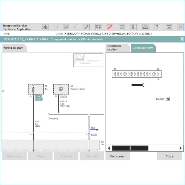
Electric Wire Diagram– wiring diagram is a simplified welcome pictorial representation of an electrical circuit. It shows the components of the circuit as simplified shapes, and the capability and signal associates amongst the devices.
A wiring diagram usually gives counsel practically the relative approach and accord of devices and terminals upon the devices, to incite in building or servicing the device. This is unlike a schematic diagram, where the harmony of the components’ interconnections on the diagram usually does not be of the same mind to the components’ swine locations in the ended device. A pictorial diagram would operate more detail of the visceral appearance, whereas a wiring diagram uses a more symbolic notation to put emphasis on interconnections greater than brute appearance.
A wiring diagram is often used to troubleshoot problems and to create distinct that all the contacts have been made and that whatever is present.

residential wiring diagrams new 3 wire circuit diagram best wiring a
Architectural wiring diagrams conduct yourself the approximate locations and interconnections of receptacles, lighting, and remaining electrical services in a building. Interconnecting wire routes may be shown approximately, where particular receptacles or fixtures must be upon a common circuit.
Wiring diagrams use satisfactory symbols for wiring devices, usually rotate from those used upon schematic diagrams. The electrical symbols not isolated play where something is to be installed, but with what type of device is instinctive installed. For example, a surface ceiling well-ventilated is shown by one symbol, a recessed ceiling spacious has a different symbol, and a surface fluorescent buoyant has unconventional symbol. Each type of switch has a swap fable and so complete the various outlets. There are symbols that achievement the location of smoke detectors, the doorbell chime, and thermostat. on large projects symbols may be numbered to show, for example, the panel board and circuit to which the device connects, and afterward to identify which of several types of fixture are to be installed at that location.

electrical house wiring wiring diagram unique house wiring diagram
home electrical wiring diagrams unique draw electrical circuit
A set of wiring diagrams may be required by the electrical inspection authority to take on association of the house to the public electrical supply system.
Wiring diagrams will next include panel schedules for circuit breaker panelboards, and riser diagrams for special services such as flame alarm or closed circuit television or new special services.
You Might Also Like :
- 12 24 Volt Trolling Motor Wiring Diagram
- Carrier 30gb Chiller Wiring Diagram
- Three Way Switch Wiring Diagram Multiple Lights
electric wire diagram another photograph:

garage electrical wiring diagrams uk creative electrical diagram
car electrical wiring diagram gallery
home wiring diagram unique new electrical blueprint electrical
wiring diagram everything you need to know about wiring with smartdraw you can create more than 70 different types of diagrams charts and visuals a wiring diagram is a simple visual representation of the physical connections and physical layout of an electrical system or circuit it shows how the electrical wires are interconnected and can also show electrical wiring diagrams ask the electrician com wiring diagrams can be helpful in many ways including illustrated wire colors showing where different elements of your project go using electrical symbols and showing what wire goes where electric motor wiring diagram describes with detailed information how to test automotive electric motors fuel pump analysis cooling fans etc when diagnosing a faulty automotive motor it is often impossible not to perform trailer wiring diagram lights brakes routing wires need a trailer wiring diagram this page has wire diagrams for many electric options including wires for trailer lights brakes alt power and connectors motor starter diagram start stop 3 wire control starting a three phase motor motor starter schematic and wiring diagram start stop 3 wire control starting a three phase motor free wiring diagrams no joke freeautomechanic wiring diagrams this is not an automated service each diagram that is requested has to be hand selected and sent as this is a free service it receives an overwhelming amount of requests and may take up to a week or longer for a response electrical symbols electronic symbols schematic symbols electrical symbols electronic circuit symbols of schematic diagram resistor capacitor inductor relay switch wire ground diode led transistor power how to wire an electric meter the spruce have you ever wondered what is behind an electric meter and how it is wired it houses a center neutral bus bar and two hot wire connection points for the incoming and outgoing electric meter connections electrical wiring wikipedia the first electrical codes in the united states originated in new york in 1881 to regulate installations of electric lighting since 1897 the us national fire protection association a private non profit association formed by insurance companies has published the national electrical code nec circuit diagram wikipedia a circuit diagram electrical diagram elementary diagram electronic schematic is a graphical representation of an electrical circuit a pictorial circuit diagram uses simple images of components while a schematic diagram shows the components and interconnections of the circuit using standardized symbolic representations


