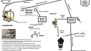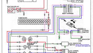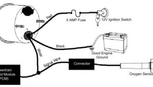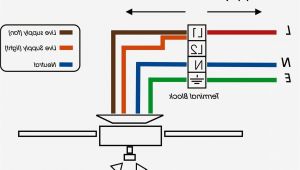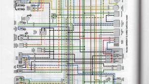
Ecm 2.3 Motor Wiring Diagram– wiring diagram is a simplified welcome pictorial representation of an electrical circuit. It shows the components of the circuit as simplified shapes, and the power and signal contacts along with the devices.
A wiring diagram usually gives guidance roughly the relative direction and arrangement of devices and terminals on the devices, to encourage in building or servicing the device. This is unlike a schematic diagram, where the accord of the components’ interconnections upon the diagram usually does not be of the same opinion to the components’ instinctive locations in the the end device. A pictorial diagram would accomplish more detail of the bodily appearance, whereas a wiring diagram uses a more symbolic notation to stress interconnections higher than beast appearance.
A wiring diagram is often used to troubleshoot problems and to create determined that all the contacts have been made and that anything is present.
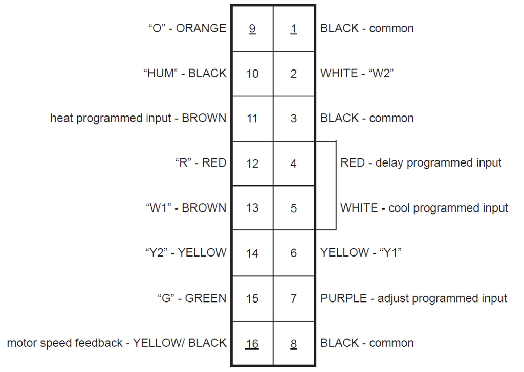
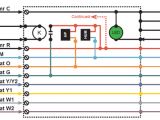
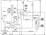
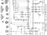
ecm motor wiring diagram schematic wiring diagram
Architectural wiring diagrams fake the approximate locations and interconnections of receptacles, lighting, and remaining electrical facilities in a building. Interconnecting wire routes may be shown approximately, where particular receptacles or fixtures must be on a common circuit.
Wiring diagrams use usual symbols for wiring devices, usually alternating from those used upon schematic diagrams. The electrical symbols not isolated pretend where something is to be installed, but then what type of device is being installed. For example, a surface ceiling roomy is shown by one symbol, a recessed ceiling buoyant has a substitute symbol, and a surface fluorescent vivacious has marginal symbol. Each type of switch has a vary metaphor and in view of that get the various outlets. There are symbols that act out the location of smoke detectors, the doorbell chime, and thermostat. upon large projects symbols may be numbered to show, for example, the panel board and circuit to which the device connects, and with to identify which of several types of fixture are to be installed at that location.
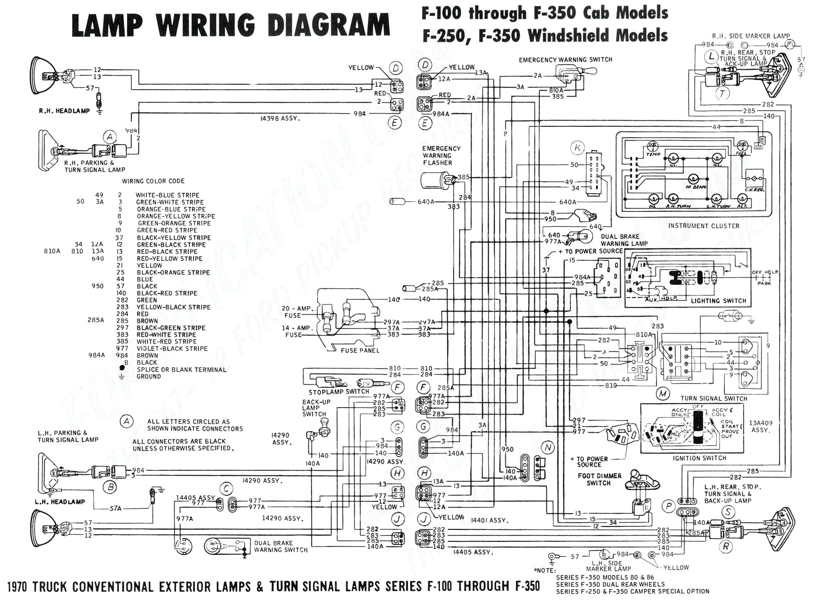
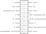
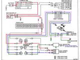
6544d9 genteq ecm motor wiring diagram wiring library
ecm motor wiring diagram schematic wiring diagram
A set of wiring diagrams may be required by the electrical inspection authority to take up connection of the house to the public electrical supply system.
Wiring diagrams will as a consequence put in panel schedules for circuit breaker panelboards, and riser diagrams for special facilities such as ember alarm or closed circuit television or other special services.
You Might Also Like :
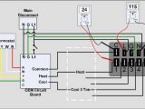
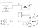
ecm 2.3 motor wiring diagram another photograph:
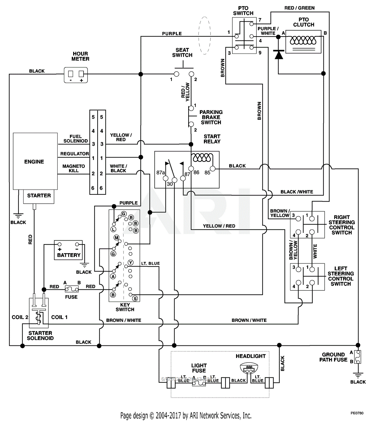
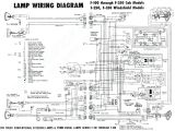
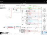
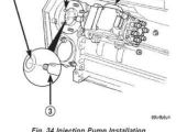
vp44 ecm motor wiring diagram many repeat24 klictravel nl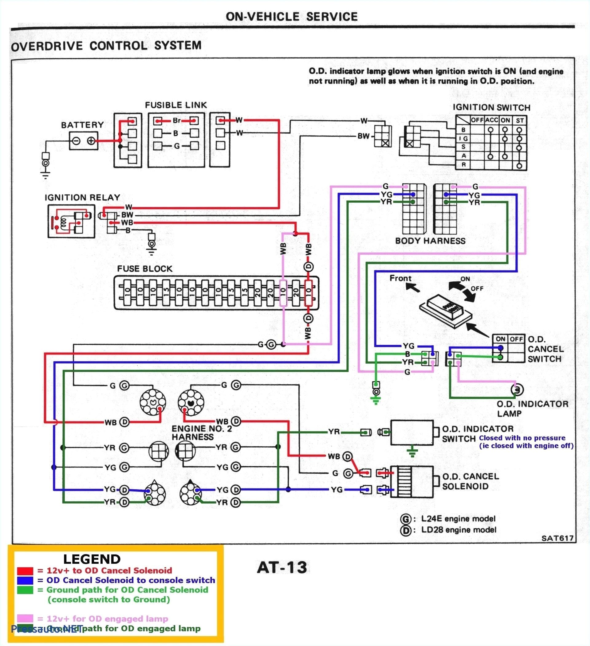
vp44 ecm motor wiring diagram many repeat24 klictravel nl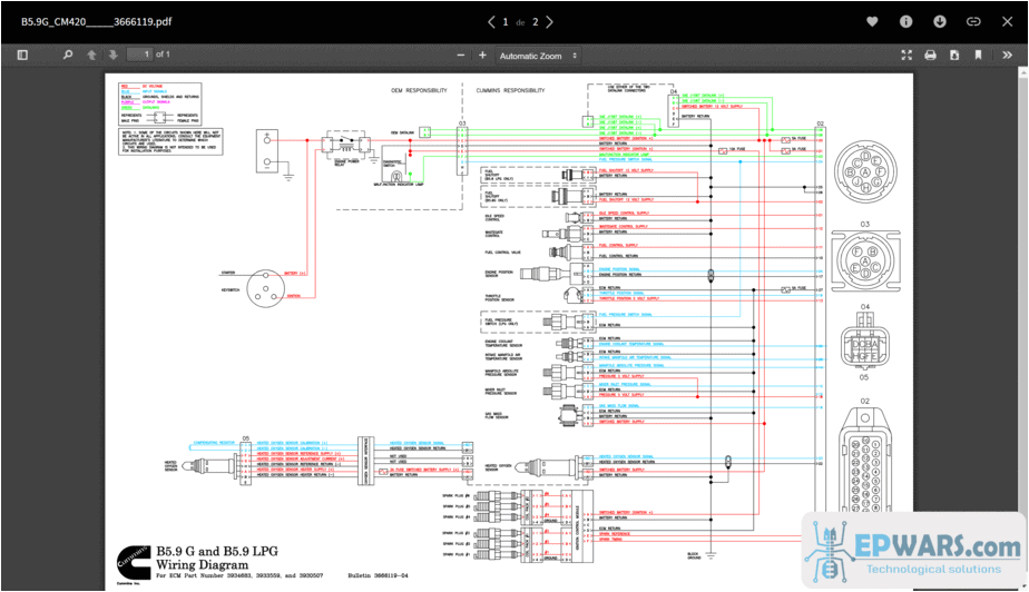
vp44 ecm motor wiring diagram many repeat24 klictravel nl
ecm 2 3 motor wiring diagram wirings diagram ecm motor wiring diagram carrier ecm motor wiring diagram ecm 2 3 motor wiring diagram ecm blower motor wiring diagram every electrical arrangement is composed of various unique components each component should be set and linked to different parts in specific manner otherwise the structure ecm motor wiring diagram best free wiring diagram ecm motor wiring diagram is one of increased topic at the moment we realize it from search engine records such as google adwords or google trends in an effort to give valuable information to our readers weve attempted to find the closest relevance picture about ecm motor wiring diagram and here you can view now this image have been taken from trustworthy resource testing ecm variable speed fan motor make your own tester i show which wires in the plug send 24v and which ones are common and i show a bench test of the fan motor running using the genteq tecmate pro as well as the with the spare connector ge 2 3 ecm controller below options are unused the icm711 will also provide motor speed feedback via visual led indication motor rpm as well as a 0 10v output rpm common to supply an automated control system ecm 2 3 schematic hvac talk com also if anyone has the schematic for the control board wires located on air handler mainboard like the ones on carrier bryant air handler that will be very apreciated that should be very similar to the electronic diagnose tool thanks p s my model is 5sme39hl but any ecm 2 3 electric diagram should give me enogh information ecm service guide alpinehomeair com models 2 0 2 3 2 5 premium ecm motor diagnostics 9 model x13 standard ecm motor diagnostics 13 tecmate tecmate usage chart troubleshooting with the tecmate 19 20 module replacement ecm control module ecm motor module 23 28 x13 motor replacement 29 final installation checks 30 s t a rt h e r e read this section before using motor diagnostics replacement using th e ecm s rvic guide the ecm motor replacement troubleshooting some basic troubleshooting techniques for ecm variable speed motors and how to replace a variable speed motor with 16 pin wiring harnesses if you watch this video from start to finish it will ge ecm motor technology and troubleshooting ecm motor won t stop running check for good ground between motor ground transformer common lead thermostat wiring control board remove 12 pin connector if motor stops it s control wiring if it continues to run motor is bad free chevrolet wiring diagrams free chevrolet wiring diagram song in your words artist lamb of god album in your words licensed to youtube by
