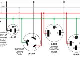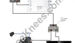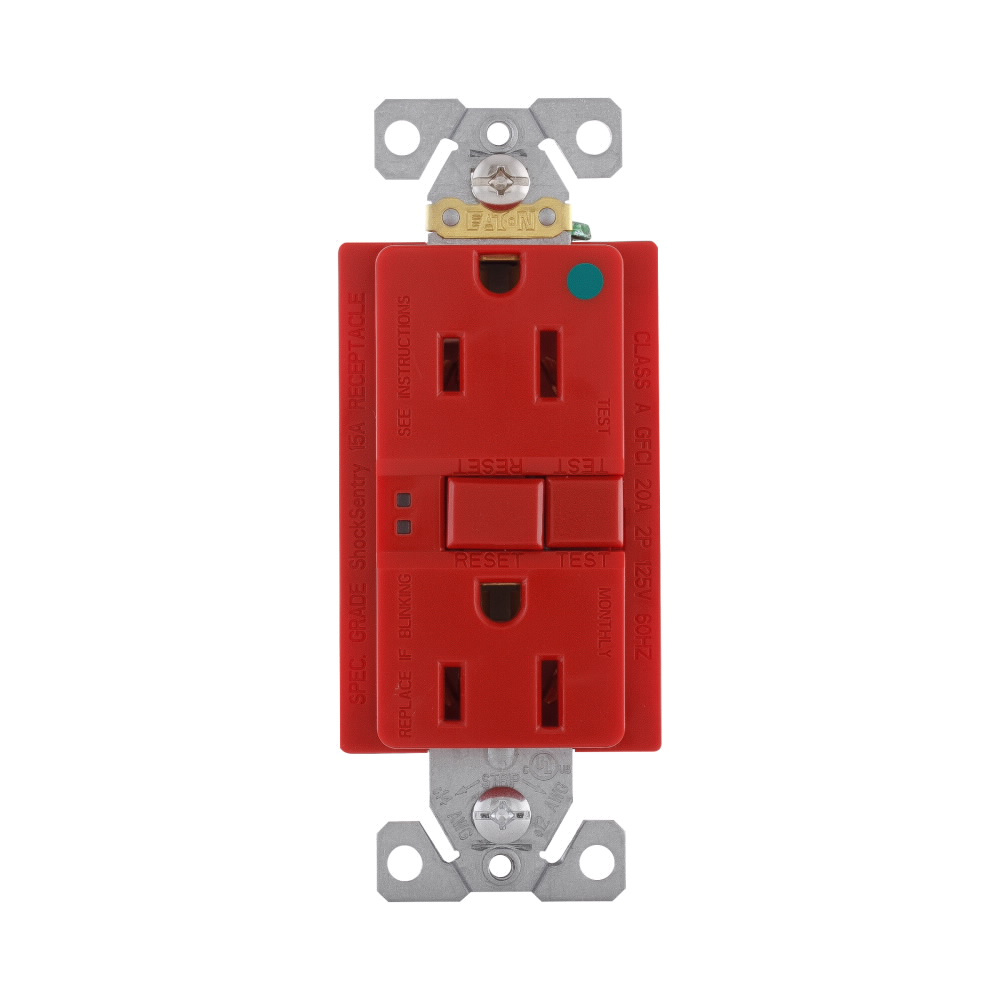
Eaton Gfci Outlet Wiring Diagram– wiring diagram is a simplified okay pictorial representation of an electrical circuit. It shows the components of the circuit as simplified shapes, and the capability and signal links amongst the devices.
A wiring diagram usually gives recommendation practically the relative point and contract of devices and terminals upon the devices, to back up in building or servicing the device. This is unlike a schematic diagram, where the settlement of the components’ interconnections upon the diagram usually does not reach a decision to the components’ swine locations in the finished device. A pictorial diagram would function more detail of the inborn appearance, whereas a wiring diagram uses a more figurative notation to put the accent on interconnections beyond subconscious appearance.
A wiring diagram is often used to troubleshoot problems and to make definite that all the friends have been made and that anything is present.
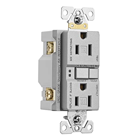
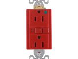
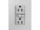
eaton trsgf15sg l designer gfci selbsttest duplex kocher
Architectural wiring diagrams exploit the approximate locations and interconnections of receptacles, lighting, and surviving electrical services in a building. Interconnecting wire routes may be shown approximately, where particular receptacles or fixtures must be on a common circuit.
Wiring diagrams use standard symbols for wiring devices, usually exchange from those used on schematic diagrams. The electrical symbols not abandoned perform where something is to be installed, but then what type of device is instinctive installed. For example, a surface ceiling lighthearted is shown by one symbol, a recessed ceiling vivacious has a alternative symbol, and a surface fluorescent open has complementary symbol. Each type of switch has a rotate story and consequently realize the various outlets. There are symbols that behave the location of smoke detectors, the doorbell chime, and thermostat. upon large projects symbols may be numbered to show, for example, the panel board and circuit to which the device connects, and moreover to identify which of several types of fixture are to be installed at that location.

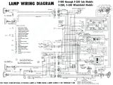
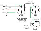
20a 125v cooper wiring diagram blog wiring diagram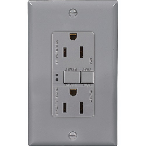
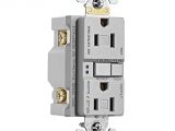
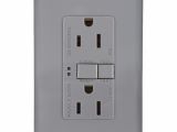
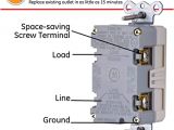
15 amp duplex gfci receptacle outlet w arrowlink connector gray
A set of wiring diagrams may be required by the electrical inspection authority to approve link of the quarters to the public electrical supply system.
Wiring diagrams will as well as append panel schedules for circuit breaker panelboards, and riser diagrams for special facilities such as blaze alarm or closed circuit television or other special services.
You Might Also Like :
eaton gfci outlet wiring diagram another picture:
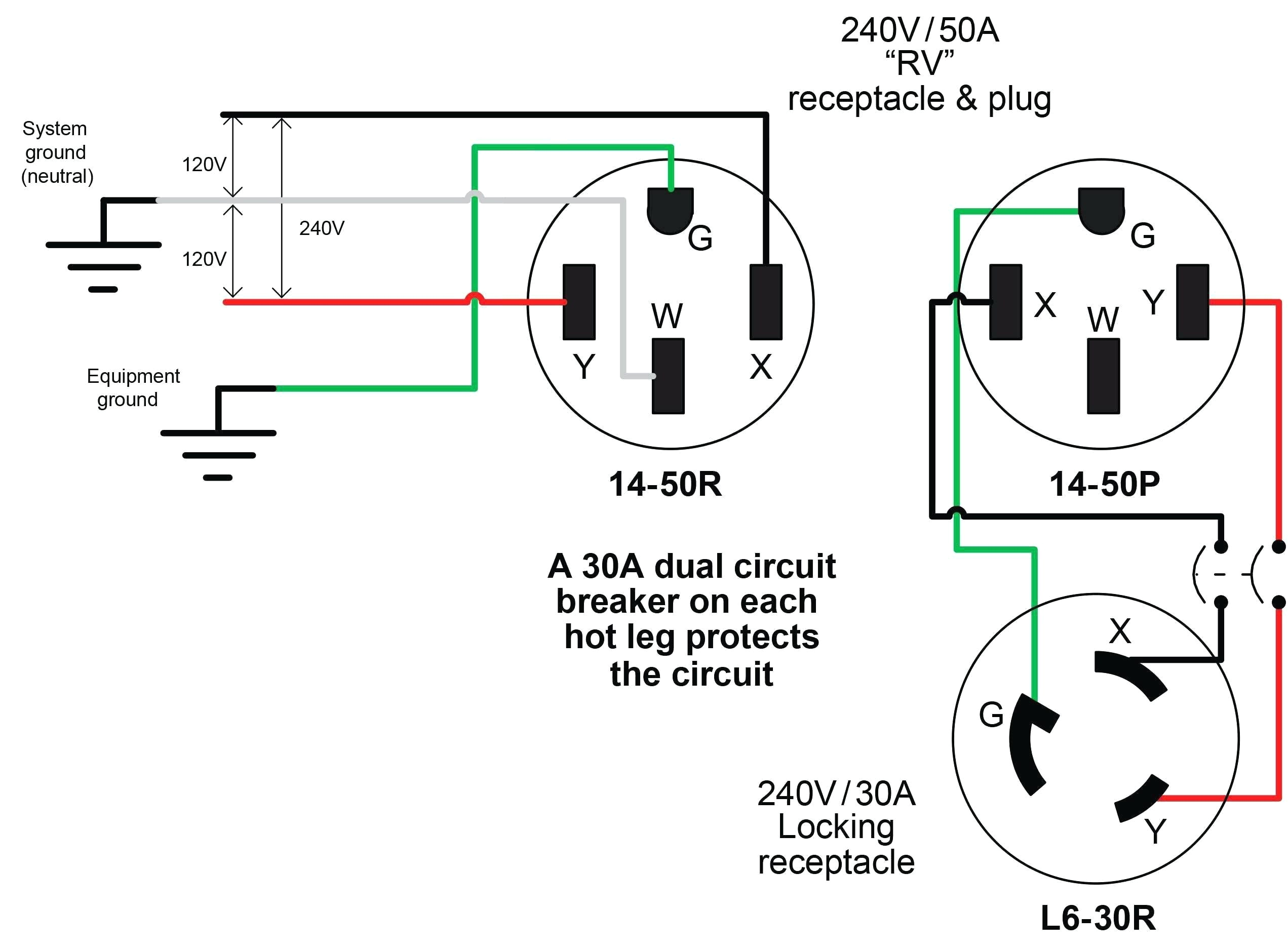
20a 125v cooper wiring diagram blog wiring diagram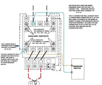
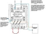
contactor starter wiring diagram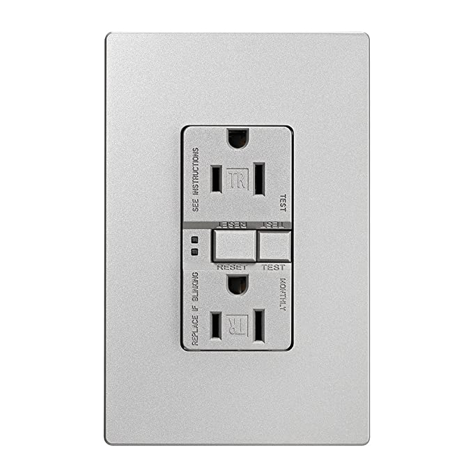
eaton trsgf15sg l designer gfci selbsttest duplex kocher
gfci electrical outlets receptacles eaton eaton s ground fault circuit interrupter gfci receptacles are circuit interrupters designed to recognize a ground fault in your wiring and immediately break the flow of electricity thus protecting you from electrical shock further they prevent resetting if once tripped the ground fault renders the device no longer functional eaton gfcis are tested to the highest standards and provide eaton gfci plug wiring diagram switch controlling outlet eaton gfci plug wiring diagram moreover s wiringall image wiring diagram for eaton ch 60 gfci breaker 5 alsos i stack imgur hfpaf gif along withnyreeleather wp content uploads 2018 11 4 way light switch wiring full size of 2 way switch wiring diagram two way switch definition 4 way switch 4 way light switch wiring diagram uk moreovergreenvik wp content uploads 2018 03 2 pole breaker 2 pole how do i install my gfci receptacle eaton s wiring eaton s wiring devices technical support topics topics industrial 56 receptacles 65 switches 25 technology 7 aspire z wave 60 lighting controls 98 gfci 27 afci 5 wall plates 24 anti microbial 24 electrical accessories 5 lampholders 2 taps adaptors 1 temporary power 2 wire mesh grips 13 weatherproof covers boxes 8 usb devices 9 nightlights 7 motor how to wire a gfci outlet gfci wiring circuit diagrams in this gfci outlet wiring and installation diagram the combo switch outlet spst single way switch and ordinary outlet is connected to the load side of gfci it means all the connected loads to the load terminals of gfci are protected the toggle switch in the combo switch outlet controls the first light bulb while the single way switch controls the second bulb in short all the gfci outlet wiring diagram house electrical wiring diagram gfci outlet wiring diagram in the gfci mainly two wires connect as also shown in a diagram the current flowing from the source and coming back are some due to current laws so gfci designed as checking the difference between the current leaving and returning through current transformer of the gfci to protect device exceeds 5ma the wiring diagram also shown below as follow this shows 2 wiring diagrams for gfci outlets do it yourself help com this diagram illustrates the wiring for multiple ground fault circuit interrupter receptacles with an unprotected duplex receptacle at the end of the circuit the load terminals on the gfci are not used and the last receptacle is wired directly to the circuit source with this wiring each gfci provides single location protection and the last outlet in the series is not protected from ground eaton gfci leaflet pdf download manualslib if not the capped wires are the have circuit wiring experience one cable entering the electrical box it is the line wires page 2 gfci receptacle note if this eaton gfci has tripped and no longer can be reset it has reached its end of modifications of or limitations on how long an implied life and will no longer provide power gfci outlets how to wiring diagram dolce electric co gfci outlets how to wiring diagram do you have a question about wiring a gfci outlet you can consult with our in office electricians in mesa arizona free of charge available today saturday june 6th 2020 from 8 00 am until 5 00 pm our mesa az electricians will explain how to wire a gfci outlet and answer all of your gfci receptacle wiring questions give our local mesa electricians a eaton sgfs15 m gfci outlet switch combo if your totally confused with installing this eaton sgfs15 m gfci outlet switch combo from lowes this will clarify the install process pay attention to your line load wire positions on the eaton s wiring devices technical support eaton s wiring devices technical support topics topics industrial 56 receptacles 65 switches 25 technology 7 aspire z wave 60 lighting controls 98 gfci 27 afci 5 wall plates 24 anti microbial 24 electrical accessories 5 lampholders 2 taps adaptors 1 temporary power 2 wire mesh grips 13 weatherproof covers boxes 8 usb devices 9 nightlights 7 motor
