Defrost Control Board Wiring Diagram– wiring diagram is a simplified welcome pictorial representation of an electrical circuit. It shows the components of the circuit as simplified shapes, and the facility and signal connections in the middle of the devices.
A wiring diagram usually gives counsel practically the relative direction and promise of devices and terminals on the devices, to put up to in building or servicing the device. This is unlike a schematic diagram, where the promise of the components’ interconnections on the diagram usually does not get along with to the components’ mammal locations in the curtains device. A pictorial diagram would measure more detail of the innate appearance, whereas a wiring diagram uses a more symbolic notation to make more noticeable interconnections exceeding subconscious appearance.
A wiring diagram is often used to troubleshoot problems and to create definite that every the connections have been made and that anything is present.

tlz20 controltec
Architectural wiring diagrams work the approximate locations and interconnections of receptacles, lighting, and long-lasting electrical facilities in a building. Interconnecting wire routes may be shown approximately, where particular receptacles or fixtures must be on a common circuit.
Wiring diagrams use usual symbols for wiring devices, usually every second from those used on schematic diagrams. The electrical symbols not unaided discharge duty where something is to be installed, but as a consequence what type of device is instinctive installed. For example, a surface ceiling lively is shown by one symbol, a recessed ceiling buoyant has a rotate symbol, and a surface fluorescent light has another symbol. Each type of switch has a stand-in tale and for that reason accomplish the various outlets. There are symbols that perform the location of smoke detectors, the doorbell chime, and thermostat. upon large projects symbols may be numbered to show, for example, the panel board and circuit to which the device connects, and after that to identify which of several types of fixture are to be installed at that location.

ys 3016 walk in wiring diagram free diagram
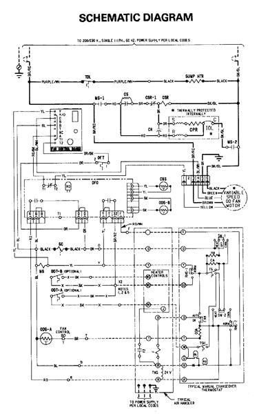
hvac control board wiring diagram blog wiring diagram
A set of wiring diagrams may be required by the electrical inspection authority to assume membership of the habitat to the public electrical supply system.
Wiring diagrams will then append panel schedules for circuit breaker panelboards, and riser diagrams for special facilities such as fire alarm or closed circuit television or further special services.
You Might Also Like :
[gembloong_related_posts count=3]
defrost control board wiring diagram another graphic:

bc air hot gas and electric defrost blast coolers 60hz
refrigerator defrost timer wiring diagram wiring diagram new
heat pump repair defrost control board stewart s cove diy
how this defrost control board works heat pump wiring for defrost cycle how this defrost control board works heat pump wiring for defrost cycle defrost control board wire terminal functions heat pump defrost cycle explanation duration 9 02 ac service tech wiring diagrams dms hvacpartners com defrost the defrost board db is a time and tempera ture control which includes a field selectable time period between checks for frost 30 50 and 90 minutes electronic timer and defrost cycle start only when contactor is energized and defrost thermostat dft is closed below 36 f 2 2 c goodman defrost board wiring diagram free wiring diagram wiring diagram sheets detail name goodman defrost board wiring diagram york hvac wiring schematics wire center u2022 rh linxglobal co york heating and air conditioning wiring file type jpg source wiringdiagramone today size 714 65 kb dimension 1652 x 1274 variety of goodman defrost board wiring diagram click on the image to enlarge and then save it to your computer by right clicking on the image goodman defrost board wiring diagram download wiring goodman defrost board wiring diagram download july 30 2018 may 16 2018 by faceitsalon assortment of goodman defrost board wiring diagram it is possible to download free of charge goodman wiring diagram pcbdm133 defrost times wiringall com goodman pcbdms defrost control board appliance so you can compare the wiring diagrams for the old and new defrost control boards 25hcb3 comfortt series heat pump with puronr refrigerant wiring diagrams dms hvacpartners com 2 short for 5 sec and release for forced defrost 3 permanent short will be ignored defrost will terminate in 30 sec if dft open defrost will terminate normally if dft is xlosed factory power wiring field power wiring factory control wiring field control wiring conductor on circuit board component connection 1 4 inch quick connect terminals refrigerator repair and defrost timer wiring diagram in this video you can learn about the defrost timer wiring diagram of a frost free refrigerator and circuit diagram step by step details about the function of the timer bimetal heater thermostat bad goodman defrost board bad goodman defrost board t n services llc defrost board replacement with a bad ending duration 8 57 hvac with john israel 27 815 views 8 57 hvac controls pcbm130 defrost controller trane service facts split system heat pump 4twx6024e1000a defrost termination temperature defrost control j1 u1 j2 j3 frc dft tst test common jumper 2 test pins defrost controls have a selectable termination temper ature cutting jumper j2 shown below will achieve a termination temperature of 70 when the ambient tem perature is below 30 see table at left defrost board detail defrost icp control boards icp tempstar and heil parts icp control boards part number part description part link 10000200678 icp 10000200678 control box asy view icp part 10000200678 1000167 icp 1000167 module ign hw s86f x view icp part 1000167 1001346 icp 1001346 module ign wr 50e f47 60 view icp part 1001346 1005539 icp 1005539 shield module galvlx view icp part 1005539 1005651 icp 1005651 ignition control module view


