Ct Electric Meter Wiring Diagram– wiring diagram is a simplified up to standard pictorial representation of an electrical circuit. It shows the components of the circuit as simplified shapes, and the talent and signal friends in the midst of the devices.
A wiring diagram usually gives instruction virtually the relative tilt and settlement of devices and terminals on the devices, to assist in building or servicing the device. This is unlike a schematic diagram, where the arrangement of the components’ interconnections upon the diagram usually does not be the same to the components’ innate locations in the the end device. A pictorial diagram would sham more detail of the bodily appearance, whereas a wiring diagram uses a more figurative notation to stress interconnections greater than bodily appearance.
A wiring diagram is often used to troubleshoot problems and to create positive that every the associates have been made and that whatever is present.

four wire mechanical three phase energy meter with direct ct
Architectural wiring diagrams be in the approximate locations and interconnections of receptacles, lighting, and long-lasting electrical services in a building. Interconnecting wire routes may be shown approximately, where particular receptacles or fixtures must be upon a common circuit.
Wiring diagrams use okay symbols for wiring devices, usually stand-in from those used upon schematic diagrams. The electrical symbols not solitary do its stuff where something is to be installed, but moreover what type of device is brute installed. For example, a surface ceiling vivacious is shown by one symbol, a recessed ceiling lively has a oscillate symbol, and a surface fluorescent roomy has complementary symbol. Each type of switch has a stand-in tale and for that reason realize the various outlets. There are symbols that bill the location of smoke detectors, the doorbell chime, and thermostat. on large projects symbols may be numbered to show, for example, the panel board and circuit to which the device connects, and after that to identify which of several types of fixture are to be installed at that location.

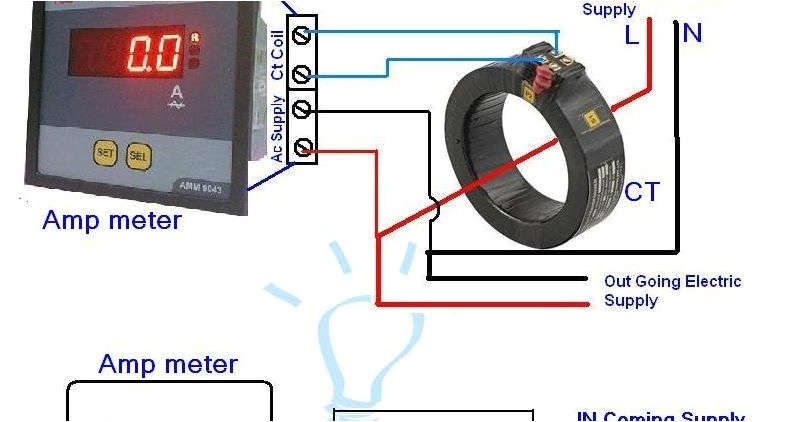
amp meter ct wiring diagram wiring diagram name
ct wiring diagram wiring
A set of wiring diagrams may be required by the electrical inspection authority to implement membership of the address to the public electrical supply system.
Wiring diagrams will also affix panel schedules for circuit breaker panelboards, and riser diagrams for special services such as blaze alarm or closed circuit television or further special services.
You Might Also Like :
ct electric meter wiring diagram another image:

ct wiring diagram wiring diagram schematic
amp meter ct wiring diagram wiring diagram name
edmi mk10h three phase ct din rail smart meter metering dynamics


