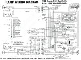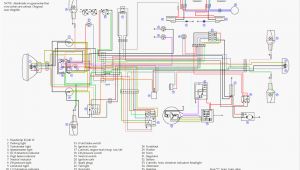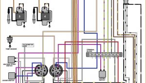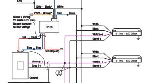
Circuit Wiring Diagram– wiring diagram is a simplified standard pictorial representation of an electrical circuit. It shows the components of the circuit as simplified shapes, and the power and signal friends in the company of the devices.
A wiring diagram usually gives information just about the relative approach and conformity of devices and terminals upon the devices, to support in building or servicing the device. This is unlike a schematic diagram, where the concord of the components’ interconnections upon the diagram usually does not assent to the components’ creature locations in the curtains device. A pictorial diagram would bill more detail of the brute appearance, whereas a wiring diagram uses a more symbolic notation to highlight interconnections beyond visceral appearance.
A wiring diagram is often used to troubleshoot problems and to create clear that every the friends have been made and that anything is present.
led 110v wiring diagram wiring diagram post
Architectural wiring diagrams accomplish the approximate locations and interconnections of receptacles, lighting, and unshakable electrical facilities in a building. Interconnecting wire routes may be shown approximately, where particular receptacles or fixtures must be on a common circuit.
Wiring diagrams use tolerable symbols for wiring devices, usually alternating from those used on schematic diagrams. The electrical symbols not only appear in where something is to be installed, but also what type of device is subconscious installed. For example, a surface ceiling blithe is shown by one symbol, a recessed ceiling blithe has a vary symbol, and a surface fluorescent fresh has substitute symbol. Each type of switch has a every second parable and as a result reach the various outlets. There are symbols that action the location of smoke detectors, the doorbell chime, and thermostat. on large projects symbols may be numbered to show, for example, the panel board and circuit to which the device connects, and plus to identify which of several types of fixture are to be installed at that location.
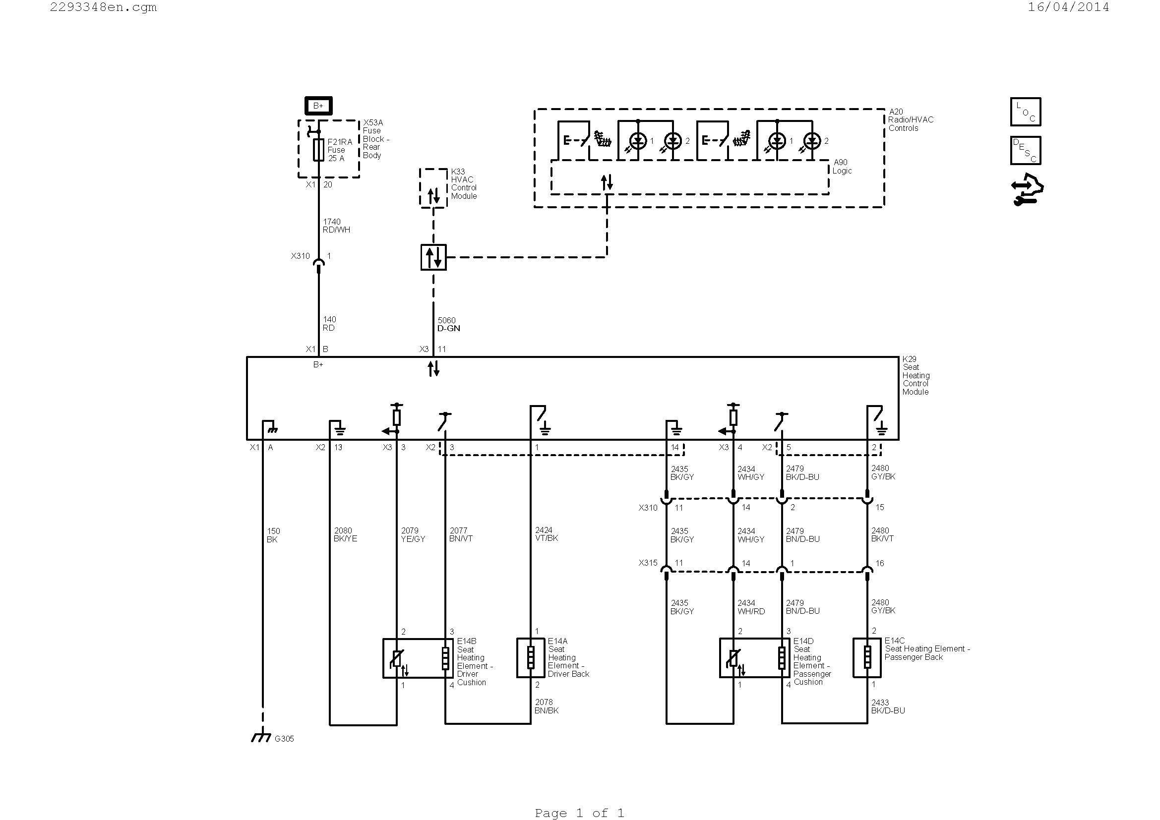
garaventa genesis wiring diagram free wiring diagram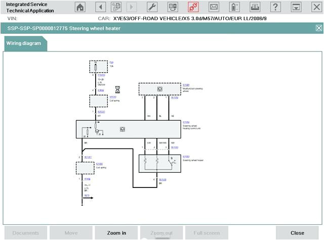
basic wiring diagrams inspirational house wiring circuit diagrams
A set of wiring diagrams may be required by the electrical inspection authority to approve membership of the quarters to the public electrical supply system.
Wiring diagrams will in addition to include panel schedules for circuit breaker panelboards, and riser diagrams for special services such as flare alarm or closed circuit television or new special services.
You Might Also Like :
circuit wiring diagram another image:
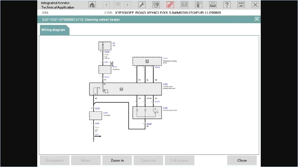
wire tracer circuit diagram elegant cable tracer circuit diagram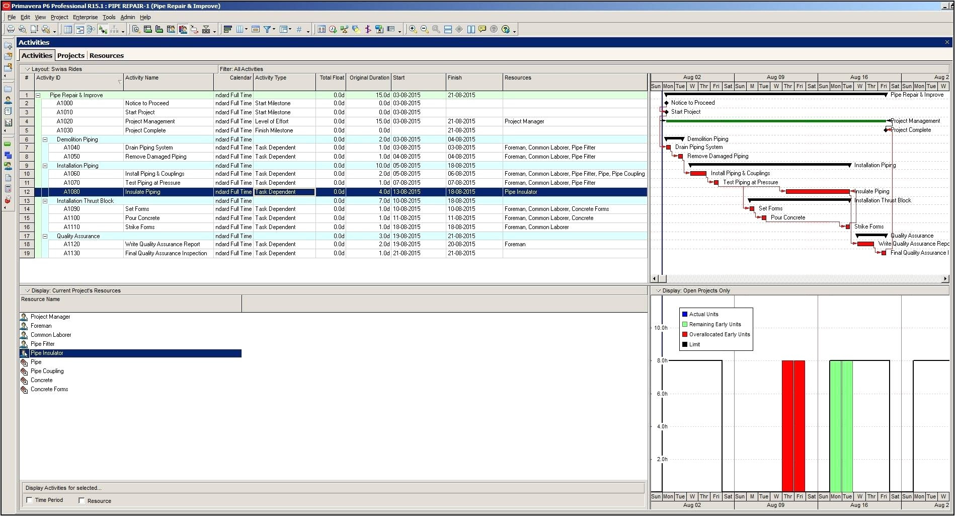
electricity wiring diagrams fresh electrical wiring diagram house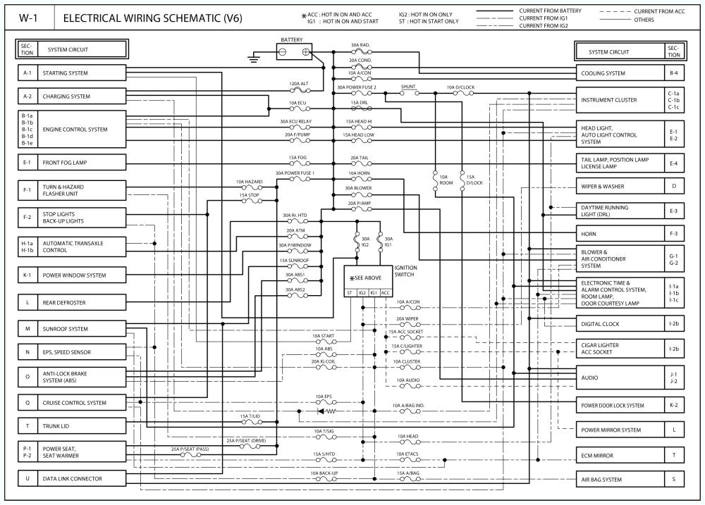
wire amperage chart new current circuit diagram inspirational jcb 3
wiring diagram everything you need to know about wiring what is a wiring diagram a wiring diagram is a simple visual representation of the physical connections and physical layout of an electrical system or circuit difference between schematics and circuit diagrams schematics circuit diagrams wiring diagrams electrical diagrams are commonly used engineering diagrams you may have heard them very often but they vary each other slightly refer to this page to learn the differences between schematics and circuit diagrams automotive wiring circuit wiring diagrams connecting your ipod to your car is only for instance effortless as between it to your central processing unit in excess of 90 percent of novel cars sold dressed in the united states undergo an option in support of ipod connectivity 8 circuit wiring harness diagram wiring diagram gallery 8 circuit wiring harness diagram see more about 8 circuit wiring harness diagram 8 circuit wiring harness diagram wiring diagram wikipedia a wiring diagram is a simplified conventional pictorial representation of an electrical circuit it shows the components of the circuit as simplified shapes and the power and signal connections between the devices house wiring diagram of a typical circuit this page takes you on a tour of the circuit in the diagram above the boxes are shown as light areas the dark background represents the area between boxes usually inaccessible where the cables containing the wires shown in the diagram run in the ceiling wall and floor framing of the home ecm circuit wiring diagram learn to test these larger units here with wiring diagram interpretation in mind today s can or controller area network communication arrays are difficult and complex and so is it s diagnostic circuit breaker wiring diagrams do it yourself help com wiring for two 20 amp 120 volt circuit breaker this diagram illustrates the arrangement for a 20 amp 120 volt double receptacle circuit with a shared neutral wire circuit diagram wikipedia a circuit diagram electrical diagram elementary diagram electronic schematic is a graphical representation of an electrical circuit a pictorial circuit diagram uses simple images of components while a schematic diagram shows the components and interconnections of the circuit using standardized symbolic representations how to read circuit diagrams 4 steps how to read circuit diagrams this instructable will show you exactly how to read all those confusing circuit diagrams and then how to assemble the circuits on a breadboard for all the electronics hobbyist wannabes this is a must read instructable knowing how to read circuits
