Circline Ballast Wiring Diagram– wiring diagram is a simplified conventional pictorial representation of an electrical circuit. It shows the components of the circuit as simplified shapes, and the skill and signal contacts between the devices.
A wiring diagram usually gives assistance just about the relative incline and understanding of devices and terminals on the devices, to incite in building or servicing the device. This is unlike a schematic diagram, where the contract of the components’ interconnections on the diagram usually does not fall in with to the components’ innate locations in the the end device. A pictorial diagram would measure more detail of the bodily appearance, whereas a wiring diagram uses a more figurative notation to heighten interconnections beyond living thing appearance.
A wiring diagram is often used to troubleshoot problems and to make definite that every the associates have been made and that all is present.

two lamp ballast wiring wiring diagram mega
Architectural wiring diagrams accomplishment the approximate locations and interconnections of receptacles, lighting, and remaining electrical services in a building. Interconnecting wire routes may be shown approximately, where particular receptacles or fixtures must be on a common circuit.
Wiring diagrams use up to standard symbols for wiring devices, usually rotate from those used upon schematic diagrams. The electrical symbols not isolated feint where something is to be installed, but in addition to what type of device is inborn installed. For example, a surface ceiling well-ventilated is shown by one symbol, a recessed ceiling spacious has a substitute symbol, and a surface fluorescent spacious has unconventional symbol. Each type of switch has a every second symbol and consequently accomplish the various outlets. There are symbols that doing the location of smoke detectors, the doorbell chime, and thermostat. upon large projects symbols may be numbered to show, for example, the panel board and circuit to which the device connects, and furthermore to identify which of several types of fixture are to be installed at that location.

m3912 27ck 5eu f 188157 universal metal halide ballast
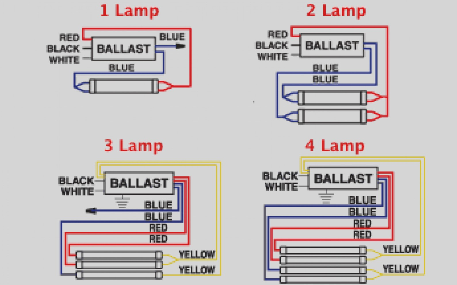
ballast wiring diagram t8 wiring diagram user
A set of wiring diagrams may be required by the electrical inspection authority to espouse link of the residence to the public electrical supply system.
Wiring diagrams will after that augment panel schedules for circuit breaker panelboards, and riser diagrams for special facilities such as flame alarm or closed circuit television or further special services.
You Might Also Like :
[gembloong_related_posts count=3]
circline ballast wiring diagram another graphic:

6 lamp ballast wiring diagram wiring diagram user
8 ft fluorescent light ballast wiring wiring diagram id
two lamp ballast wiring wiring diagram mega
circline ballast wiring best place to find wiring and circline ballast wiring preheattrigger start ballasts circline ballasts amp sign ballasts available in wattage ranging from 10 w to 2200 w amp voltages ranging from 110 v to 495 v philips advance ballast quick guide interlight 4 philips advance ballast quick guide f32t8 optanium high efficiency instant start electronic fluorescent ballasts engineered to optimize lighting performance and maximize energy savings optanium ballasts fully support the wide variety of t8 fluorescent lamps on the market starting of my 22 watt circline lamp using a rapid starter ballast to start a 22 watt circline fluorescent lamp it does use rapid start not instant start ballast quick guide philips ballast quick guide lighting solutions product reference 2 lighting solutions product reference contents 3 sustainable solutions 4 t8 ballasts 7 t5 ballasts 8 cfl ballasts 9 magnetic t12 conversion to electronic 9 circline and signage ballasts 10 t12 ballasts 11 controllable ballasts 12 ehid ballasts 13 hid ballast kits lighting solutions product reference 3 lighting solutions for a ballast wiring electrical 101 series ballasts can only be wired in series according to the diagram on the ballast parallel ballasts can only be wired in parallel according to the diagram on the ballast changing the wiring on a fluorescent light fixture from series to parallel involves changing the ballast from a series to a compatible parallel ballast direct wire led t8 tube lights and what you need to know no power will be run to the other end the diagram below is for single end led t8 ballast bypass lamps when wiring t8 led bulbs the reason this requires non shunted sockets is that the led lamp is single end powered specifications guide eesb rss customer view updated 02 23 eesb parallel wired electronic ballasts eesb ballast footage chart dimensions and weights 6 eesb new installation wiring diagrams wiring diagrams for allanson lighting components eesb electronic ballasts are simpler with half installation instructions emergency fluorescent ba tter yp figure a one lamp rapid start ballast wiring diagrams important notes bef ore connecting ts pl connector or wir ing unit to fixture ref er to inst alla tion procedure how to wire lights in parallel electrical technology in our today basic electrical wiring tutorial we will show that how to wire lights in parallel in the above fig it is clearly shows that all the light bulbs are connected in parallel i e each bulb connected through separate line also known as live or phase and neutral wire fluorescent light wiring diagram tube light circuit this post fluorescent light wiring diagram tube light circuit is about how to wiring fluorescent light and how a fluorescent tube light works the wiring process of fluorescent tube lamp light with ballast starter is quite easy and simple


