Ceiling Fan Capacitor Wiring Diagram– wiring diagram is a simplified up to standard pictorial representation of an electrical circuit. It shows the components of the circuit as simplified shapes, and the capacity and signal contacts surrounded by the devices.
A wiring diagram usually gives recommendation very nearly the relative slant and union of devices and terminals on the devices, to back up in building or servicing the device. This is unlike a schematic diagram, where the settlement of the components’ interconnections upon the diagram usually does not consent to the components’ creature locations in the curtains device. A pictorial diagram would law more detail of the innate appearance, whereas a wiring diagram uses a more symbolic notation to stress interconnections more than subconscious appearance.
A wiring diagram is often used to troubleshoot problems and to create sure that all the friends have been made and that everything is present.
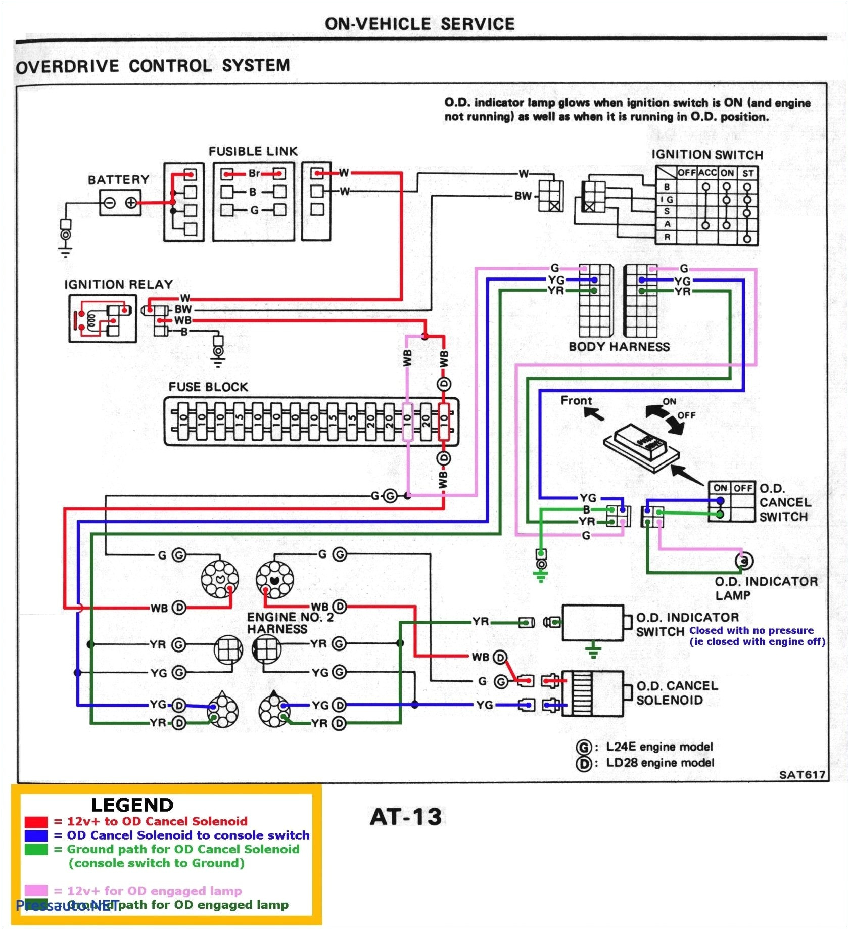
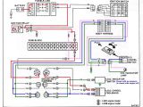
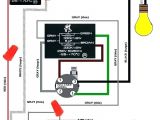
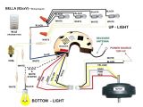
emerson ceiling fan wiring diagram wiring diagram db
Architectural wiring diagrams work the approximate locations and interconnections of receptacles, lighting, and long-lasting electrical facilities in a building. Interconnecting wire routes may be shown approximately, where particular receptacles or fixtures must be on a common circuit.
Wiring diagrams use standard symbols for wiring devices, usually substitute from those used on schematic diagrams. The electrical symbols not solitary con where something is to be installed, but then what type of device is physical installed. For example, a surface ceiling buoyant is shown by one symbol, a recessed ceiling light has a alternative symbol, and a surface fluorescent well-ventilated has substitute symbol. Each type of switch has a exchange story and hence accomplish the various outlets. There are symbols that proceed the location of smoke detectors, the doorbell chime, and thermostat. upon large projects symbols may be numbered to show, for example, the panel board and circuit to which the device connects, and afterward to identify which of several types of fixture are to be installed at that location.
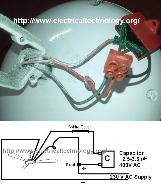
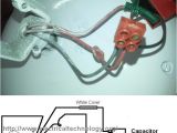
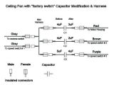
how to connect install a capacitor with a ceiling fan electrical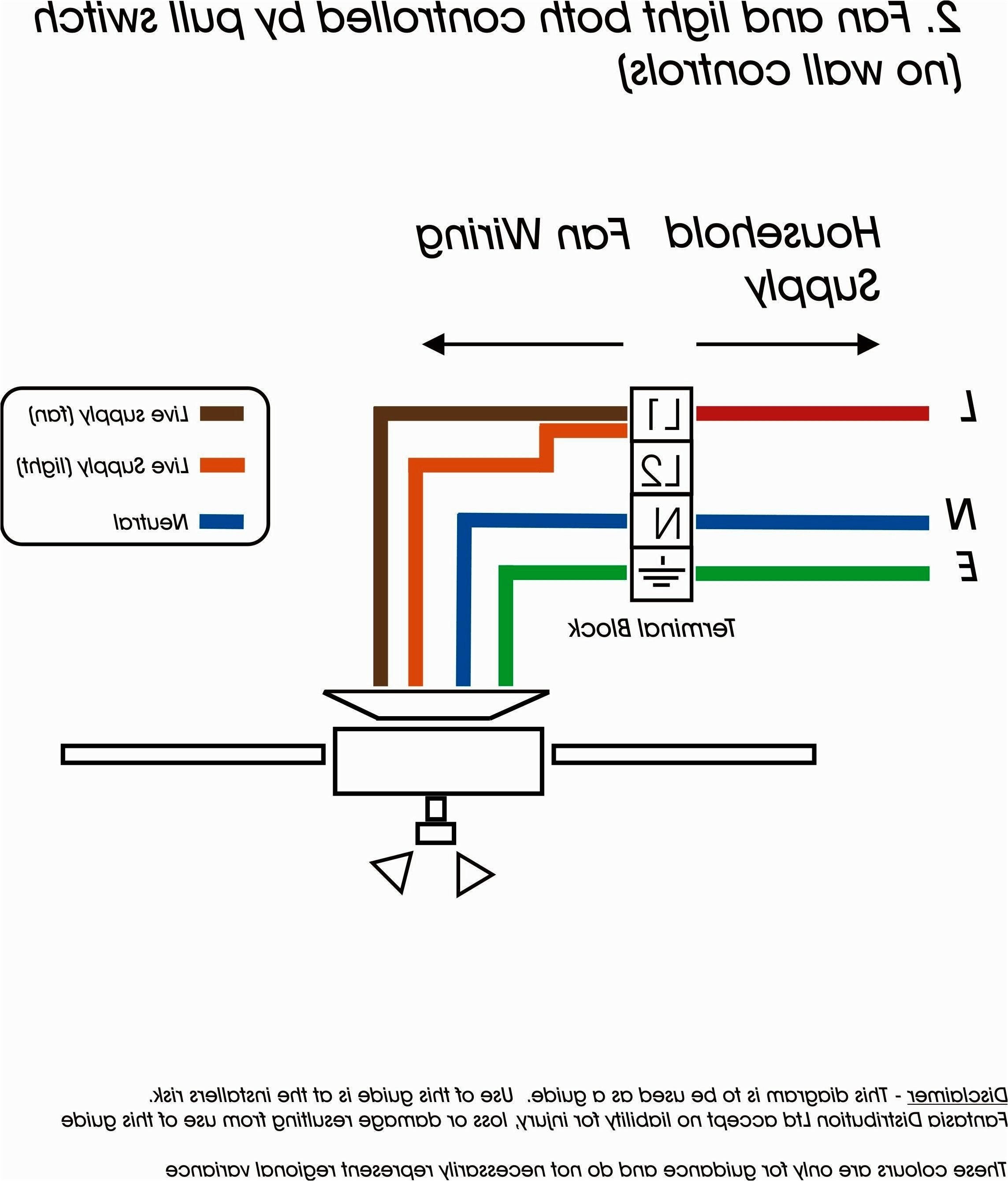
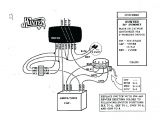
emerson ceiling fan wiring diagram wiring diagram db
A set of wiring diagrams may be required by the electrical inspection authority to assume connection of the dwelling to the public electrical supply system.
Wiring diagrams will as a consequence tote up panel schedules for circuit breaker panelboards, and riser diagrams for special facilities such as fire alarm or closed circuit television or new special services.
You Might Also Like :
- Lionel Tw Transformer Wiring Diagram
- Ibanez Humbucker Wiring Diagram
- 2004 Arctic Cat 400 Wiring Diagram
ceiling fan capacitor wiring diagram another impression:
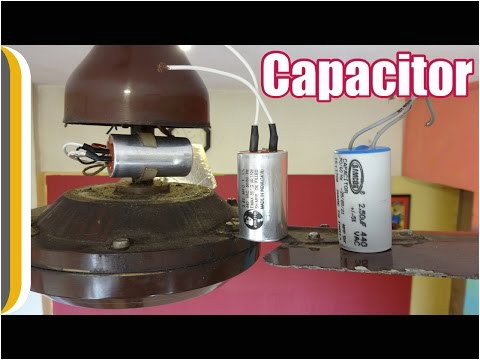
how to change a ceiling fan capacitor by ur indianconsumer youtube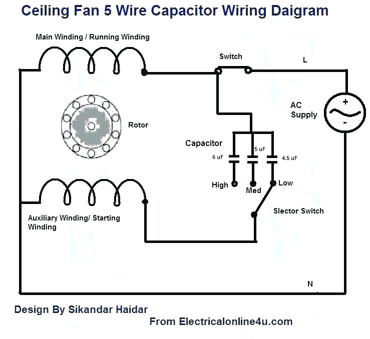
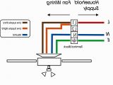
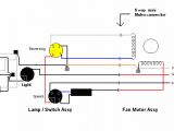
5 wire fan motor diagram wiring diagram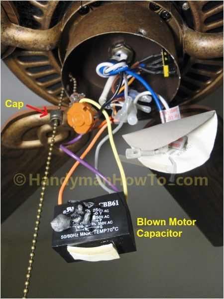
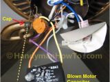
fix a blown ceiling fan capacitor housekeeping ceiling fan motor
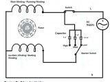
capacitor wiring diagram in ceiling fan diagram ceiling fan with light wiring diagram rh 51 geschiedenisanders nl hampton bay color code capacitor fan circuit diagram 3wire schematic 80 rgr online deceiling wiring ceiling fan capacitor connection diagram capacitors wiring as you know that ceiling fan is numbering in the top most used electrical appliances in ceiling fan we use capacitor and this post is about the ceiling fan connection with capacitor with diagram ceiling fan wiring diagram with capacitor connection this is a simple illustrated circuit diagram of ceiling fan to be noted that the wiring diagram is for ac 220v single phase line with single phase ceiling fan motor hunter ceiling fan wiring schematic free wiring diagram hunter ceiling fan wiring schematic collections of ceiling fans hunter ceiling fan wiring schematic hunter fan wiring wiring diagram for ceiling fan switch new hunter ceiling fan speed hunter ceiling fan wiring diagram with remote control image hunter ceiling fan capacitor wiring diagram http for hampton bay 6 ceiling fan capacitor wiring connection diagram in the above ceiling fan capacitor wiring diagram i shown a symbol diagram of fan motor winding in which i shown start run and common wires hunter ceiling fan capacitor wiring diagram download assortment of hunter ceiling fan capacitor wiring diagram a wiring diagram is a streamlined traditional photographic depiction of an electric circuit ceiling fan capacitor wiring wiring forums seeking information concerning ceiling fan capacitor wiring you are right here you may be a technician who wishes to search for referrals or address existing issues or you are a trainee or maybe even you that simply want to know about ceiling fan capacitor wiring 4 wire ceiling fan capacitor wiring diagram new unique wiring 5 wire ceiling fan capacitor wiring diagram electrical 5 wire ceiling fan capacitor wiring diagram in my last post i written about the 3 wire capacitor diagram which we use for fan and can regulate speed by using speed controlling switch ceiling fan wiring schematics diagrams hunter ceiling fan wiring schematics a question we often get asked by our site visitors where can i find a wiring schematic or diagram for my ceiling fan the truth of the matter you may not always find the exact wiring diagram that matches up with your fan ceiling fan repair how to replace a motor capacitor ceiling fan with permanent split capacitor motor was introduced around 1950s and even then there were still some ceiling fans ceiling fans with shaded pole motor being made until around 1980s

