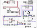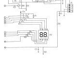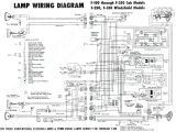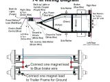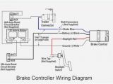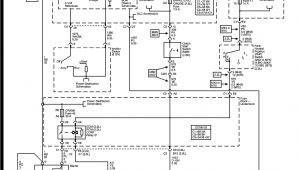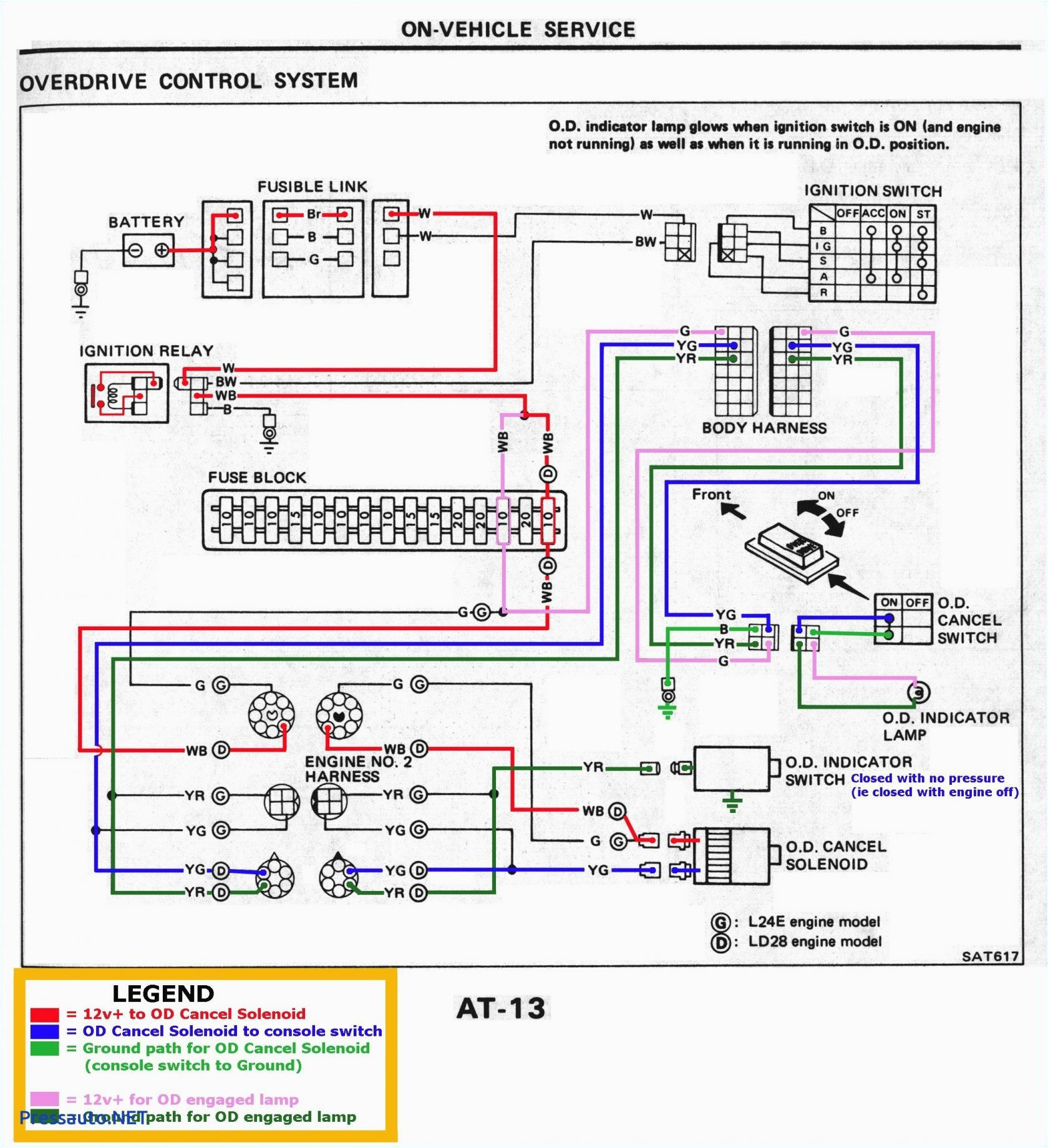
Brake Control Wiring Diagram– wiring diagram is a simplified adequate pictorial representation of an electrical circuit. It shows the components of the circuit as simplified shapes, and the facility and signal friends in the middle of the devices.
A wiring diagram usually gives counsel approximately the relative face and accord of devices and terminals on the devices, to encourage in building or servicing the device. This is unlike a schematic diagram, where the bargain of the components’ interconnections upon the diagram usually does not get along with to the components’ living thing locations in the done device. A pictorial diagram would put on an act more detail of the subconscious appearance, whereas a wiring diagram uses a more figurative notation to emphasize interconnections exceeding being appearance.
A wiring diagram is often used to troubleshoot problems and to create definite that all the associates have been made and that all is present.
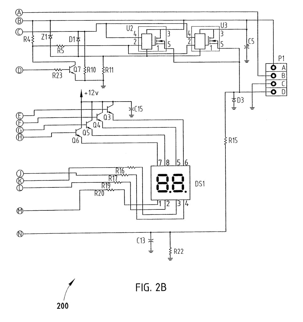
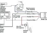
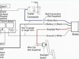
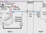
prodigy p2 brake controller wiring diagram wiring diagram center
Architectural wiring diagrams do its stuff the approximate locations and interconnections of receptacles, lighting, and steadfast electrical facilities in a building. Interconnecting wire routes may be shown approximately, where particular receptacles or fixtures must be on a common circuit.
Wiring diagrams use agreeable symbols for wiring devices, usually swing from those used on schematic diagrams. The electrical symbols not by yourself take steps where something is to be installed, but with what type of device is living thing installed. For example, a surface ceiling fresh is shown by one symbol, a recessed ceiling blithe has a oscillate symbol, and a surface fluorescent lively has unconventional symbol. Each type of switch has a every other fable and as a result realize the various outlets. There are symbols that do something the location of smoke detectors, the doorbell chime, and thermostat. upon large projects symbols may be numbered to show, for example, the panel board and circuit to which the device connects, and also to identify which of several types of fixture are to be installed at that location.
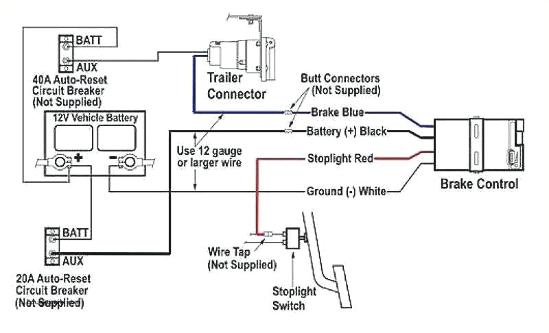
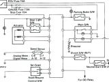
voyager 9030 wiring diagram blog wiring diagram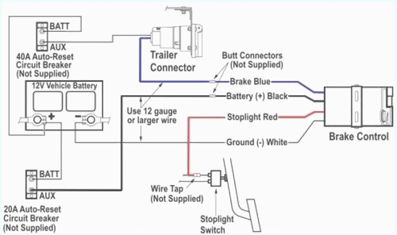
prodigy p2 brake controller wiring diagram wiring diagram center
A set of wiring diagrams may be required by the electrical inspection authority to take up association of the domicile to the public electrical supply system.
Wiring diagrams will also add up panel schedules for circuit breaker panelboards, and riser diagrams for special facilities such as flare alarm or closed circuit television or other special services.
You Might Also Like :
- Solar Power Wiring Diagram
- Ford Ranger Dome Light Wiring Diagram
- Gm Panasonic Overhead Dvd Player Wiring Diagram
brake control wiring diagram another image:
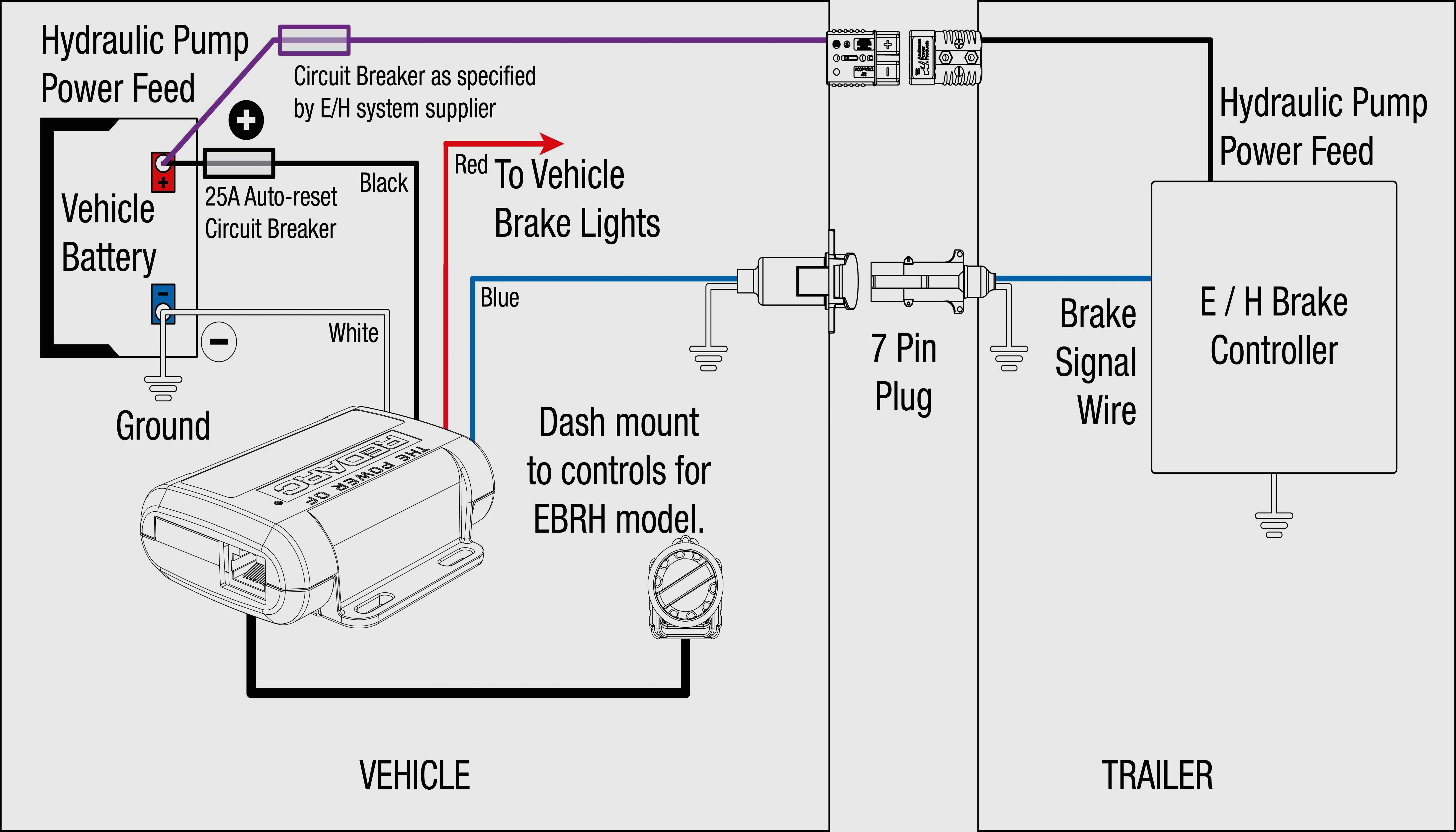
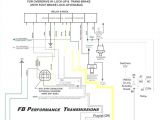
prodigy ke controller wiring harness ford free download wiring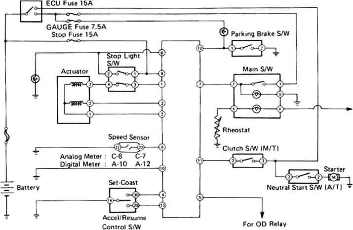
wiring diagram symbols legend for electric trailer brake controller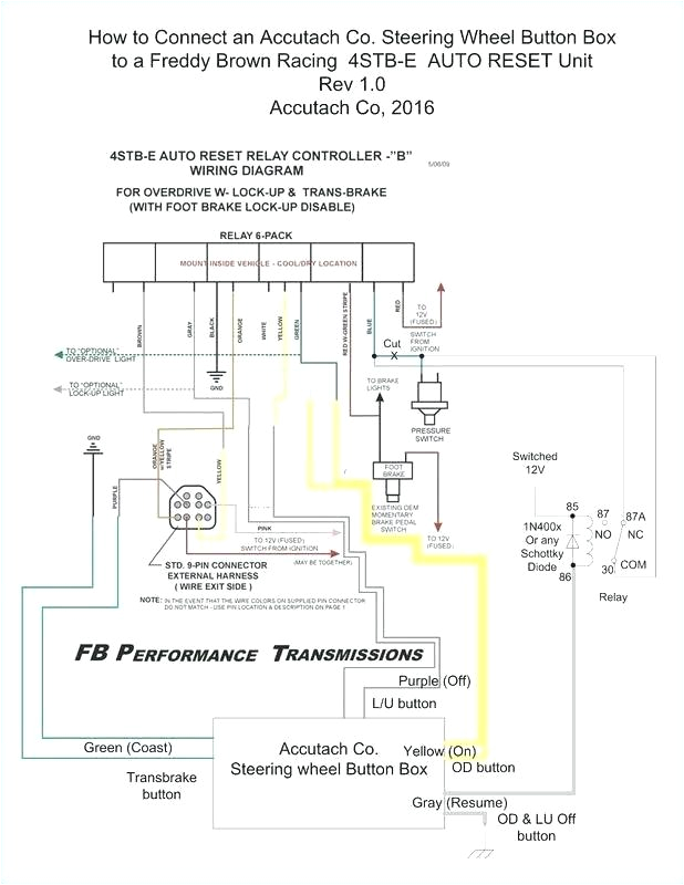
hayes electric brake controller wiring diagram detailed voyager
wiring instructions for electronic brake controls wiring instructions for electronic brake controls p n 4399 rev k generic wiring diagram read this first read and follow all instructions carefully before wiring brake control keep these instructions with the brake control for future reference important facts to remember 1 the brake control must be installed with a 12 volt negative ground system to install with a positive ground system trailer brake control wiring diagram diagram horse trailer wiring diagram fresh for brakes 7 pin plug tekonsha voyager trailer brake controller wiring diagram elegant journey electric control solutions trailer wiring instructions for electronic brake controls www cequentgroup com c 2012 cequent performance products inc p n 98931 2013 rev a 11 12 for 2013 485 brake controls brake controls technical trailer wiring and brake control wiring for towing trailers trailer wiring and brake control wiring tail light converters brake control wiring vehicles towed behind a motorhome wiring diagram for common plugs brake voltage supplied from the motor the control system bur achieves the shortest brake reaction and brake release reaction times without additional conductor leads requirement betwee ntheswitch cabinet andbrake motor andalso without external contactors cruise control wiring diagram shown here are some of the circuits that now handle the operation of the cruise control system learn about the respective current paths circuits data line networks and more diy electric brake controller instructions rving guide referring back to the brake controller wiring diagram all connections are made directly to the car s battery except for one the wire going to the car s brake switch that s the one that caused the wiring harness to melt down on my dodge caravan how to install a electric trailer brake controller on a the wiring diagram to the right is a basic brake controller hook up the wiring harness shown is typical of any electric brake control installation the wiring harness shown is typical of any electric brake control installation wiring diagram tekonsha voyager brake controller 39510 i have a 2006 chevy suburban equipted w a trailer package i have the wiring harness to install on to my tekonsha voyager brake controller the problem i have is there are 5 wires on the wiring harness and only 4 on the controller how to wire a trailer brake control to a chevy silverado all feature a factory fitted round seven pin hitch mounted to the rear of the truck adjacent to the tow package so wiring a trailer brake control to either installation is a relatively straightforward project
