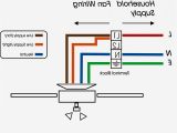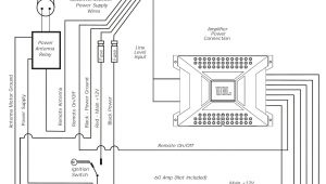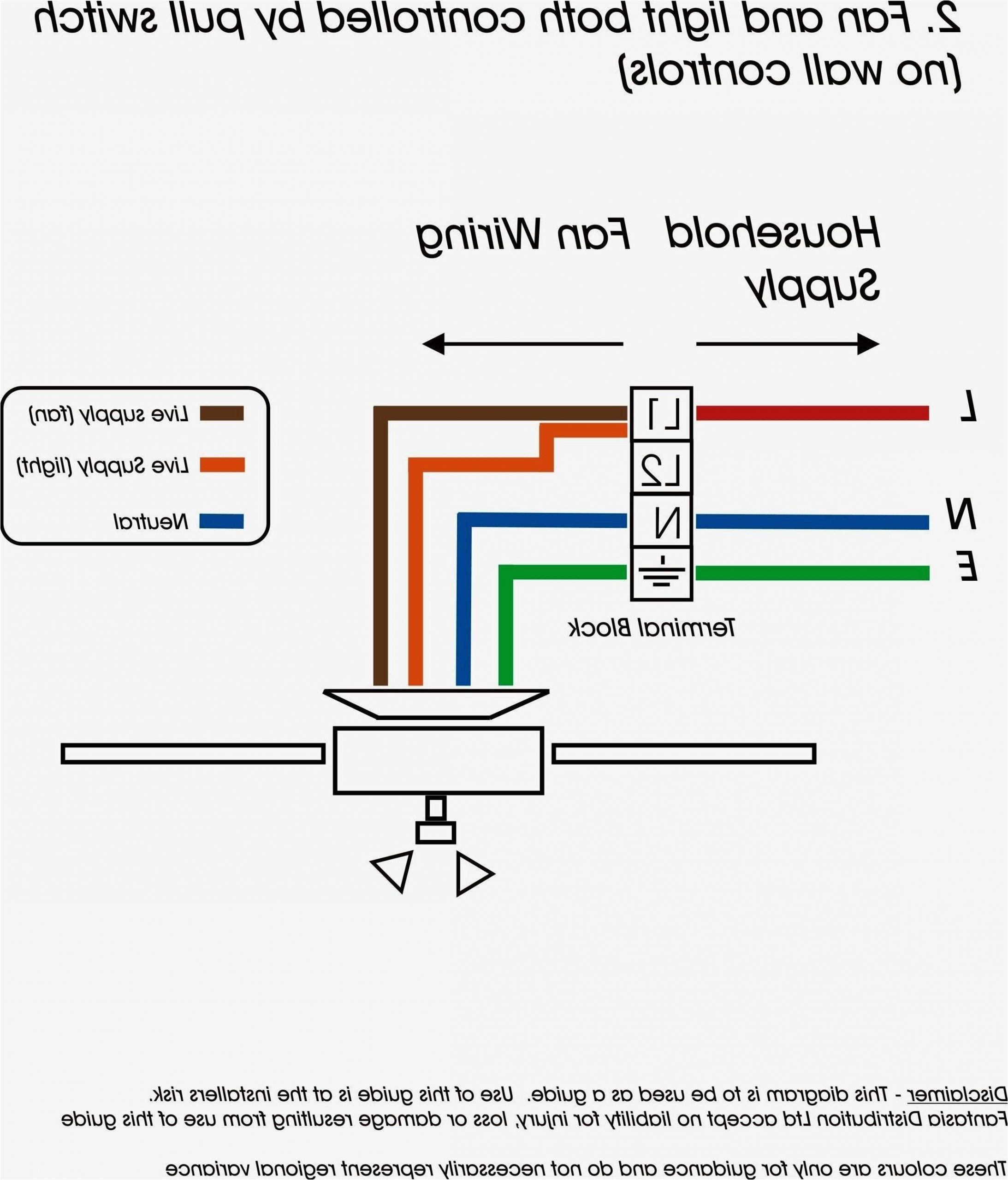
Belimo Lmb24 3 Wiring Diagram– wiring diagram is a simplified enjoyable pictorial representation of an electrical circuit. It shows the components of the circuit as simplified shapes, and the knack and signal links amongst the devices.
A wiring diagram usually gives suggestion approximately the relative slant and bargain of devices and terminals on the devices, to back in building or servicing the device. This is unlike a schematic diagram, where the accord of the components’ interconnections on the diagram usually does not approve to the components’ beast locations in the finished device. A pictorial diagram would statute more detail of the visceral appearance, whereas a wiring diagram uses a more symbolic notation to play up interconnections on top of bodily appearance.
A wiring diagram is often used to troubleshoot problems and to make sure that all the connections have been made and that all is present.
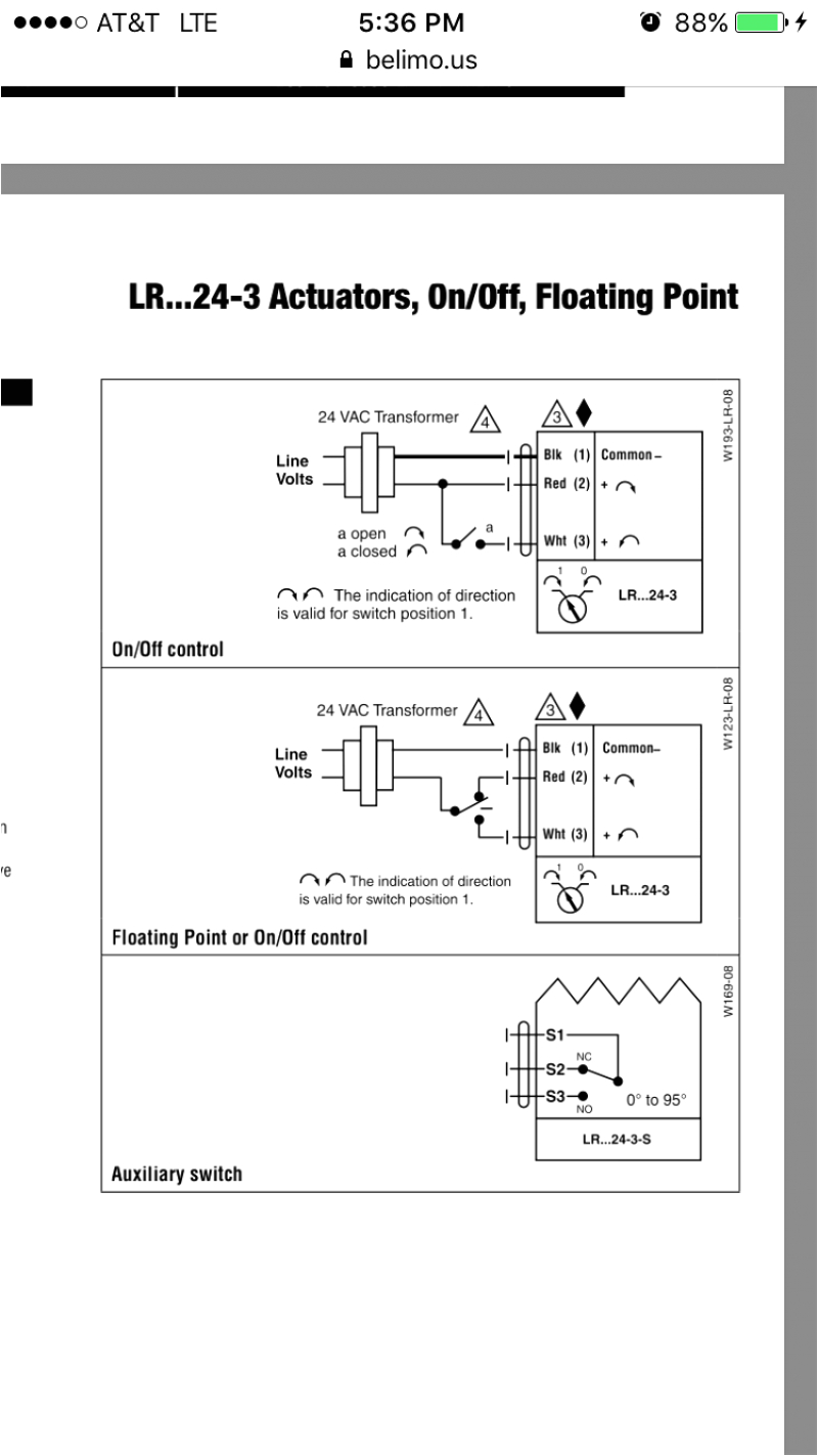
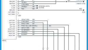
belimo wiring diagram wiring diagram
Architectural wiring diagrams comport yourself the approximate locations and interconnections of receptacles, lighting, and permanent electrical facilities in a building. Interconnecting wire routes may be shown approximately, where particular receptacles or fixtures must be upon a common circuit.
Wiring diagrams use up to standard symbols for wiring devices, usually substitute from those used upon schematic diagrams. The electrical symbols not single-handedly sham where something is to be installed, but next what type of device is instinctive installed. For example, a surface ceiling light is shown by one symbol, a recessed ceiling roomy has a every second symbol, and a surface fluorescent light has marginal symbol. Each type of switch has a exchange story and hence do the various outlets. There are symbols that show the location of smoke detectors, the doorbell chime, and thermostat. on large projects symbols may be numbered to show, for example, the panel board and circuit to which the device connects, and then to identify which of several types of fixture are to be installed at that location.
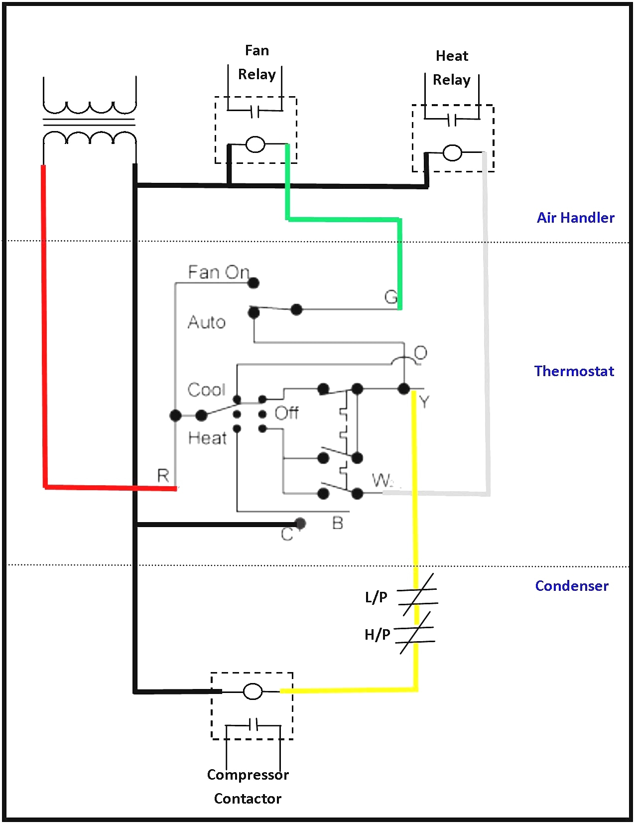
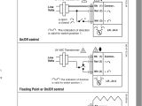
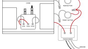
belimo valve wiring diagrams wiring diagram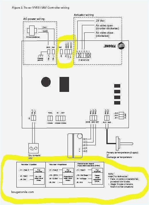
belimo wiring diagram wiring diagram
A set of wiring diagrams may be required by the electrical inspection authority to espouse association of the address to the public electrical supply system.
Wiring diagrams will also tally panel schedules for circuit breaker panelboards, and riser diagrams for special services such as fire alarm or closed circuit television or additional special services.
You Might Also Like :
belimo lmb24 3 wiring diagram another graphic:

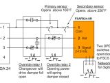
lmb24 sr belimo actuators dampers
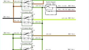
belimo wiring diagram wiring diagram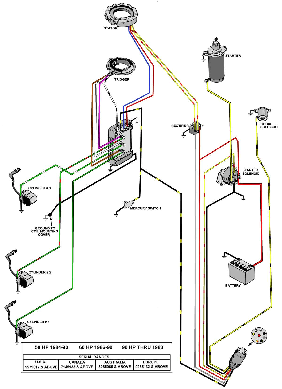
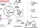
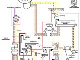
wiring diagram 50 hp mercury 3cyl 50 hp mercury outboard
lmb24 3 t technical data sheet belimo com 3 input line volts 24 vac transformer a 1 3 11 16 floating point hot com a 1 3 11 blk 1 common red 2 hot wht 3 y input line volts 24 vac transformer floating point triac source a 1 11 blk 1 common red 2 hot wht 3 y input line volts 24 vac transformer hot com 6 floating point triac sink lmb24 3 t technical data sheet belimo lrb24 3 wiring diagram free wiring diagram assortment of belimo lrb24 3 wiring diagram a wiring diagram is a simplified conventional photographic depiction of an electric circuit it reveals the components of the circuit as simplified forms and the power and also signal links in between the devices on off floating point non spring return 24 v belimo wiring diagrams installation notes provide overload protection and disconnect as required actuators may be connected in parallel power consumption and input belimo lmb24 3 t wiring diagram free wiring diagram variety of belimo lmb24 3 t wiring diagram a wiring diagram is a simplified traditional pictorial depiction of an electrical circuit it reveals the elements of the circuit as streamlined shapes as well as the power as well as signal connections between the tools belimo lmb24 3 t wiring diagram download wiring collection belimo lmb24 3 t wiring diagram download belimo lmb24 sr wiring diagrams wiring auto wiring diagrams belimo lmb24 3 t wiring diagram elegant wire diagram 3 speed belimo lmb24 3 t wiring diagram new 28 belimo actuators wiring belimo lmb24 3 t wiring diagram new 28 belimo actuators wiring lm series direct coupled actuator e controls lmb24 3 s auxiliary switch adj 0 to 100 spdt 3 a 0 5a 250 vac weight 1 4lbs 0 6 kg lmb24 3 p10 t electrical connection screw terminal for 26 to 14 ga wire feedback 10 kw 1w potentiometer lmb24 3 p5 t bulk pack only feedback 5 kw 1w potentiometer housing nema 1 ip20 lmb24 3 t lmb24 sr t technical data sheet submittal wiring diagram 1 2 3 24 vac transformer blk 1 common red 2 hot wht 3 y input 2 to 10v org 5 u output 2 to 10v line volts 2 to 10 vdc control signal 1 2 3 provide overload protection and disconnect as required actuators may be connected in parallel power consumption and input impedance must be observed lmb24 3 s t technical data sheet submittal technical data lmb24 3 on off floating power supply 24 vac 20 50 60 hz 24 vdc 10 power consumption 1 5 w 0 2 w transformer sizing 3 va class 2 power source electrical connection 3 ft 18 ga plenum rated cable 3 ft 18 ga appliance rated cable s 1 2 conduit connector overload protection electronic throughout 0 to 95 rotation control on off floating point input impedance belimo lmb24 3 installation and operation manual pdf download proportional damper actuator 24 v for 2 to 10 vdc or 4 to 20 ma control signal or 3 position on off control with minimum position potentiometer output signal of 2 to 10 vdc for position indication 2 pages
