Asco solenoid Valve Wiring Diagram– wiring diagram is a simplified usual pictorial representation of an electrical circuit. It shows the components of the circuit as simplified shapes, and the facility and signal connections between the devices.
A wiring diagram usually gives instruction nearly the relative approach and arrangement of devices and terminals on the devices, to assist in building or servicing the device. This is unlike a schematic diagram, where the conformity of the components’ interconnections on the diagram usually does not settle to the components’ beast locations in the finished device. A pictorial diagram would ham it up more detail of the beast appearance, whereas a wiring diagram uses a more figurative notation to put emphasis on interconnections greater than innate appearance.
A wiring diagram is often used to troubleshoot problems and to make clear that every the links have been made and that everything is present.

asco issc atex intrinsically safe operator hazardous area
Architectural wiring diagrams show the approximate locations and interconnections of receptacles, lighting, and unshakable electrical services in a building. Interconnecting wire routes may be shown approximately, where particular receptacles or fixtures must be upon a common circuit.
Wiring diagrams use adequate symbols for wiring devices, usually swap from those used on schematic diagrams. The electrical symbols not only performance where something is to be installed, but moreover what type of device is instinctive installed. For example, a surface ceiling buoyant is shown by one symbol, a recessed ceiling lively has a swing symbol, and a surface fluorescent buoyant has choice symbol. Each type of switch has a every second tale and suitably complete the various outlets. There are symbols that take action the location of smoke detectors, the doorbell chime, and thermostat. upon large projects symbols may be numbered to show, for example, the panel board and circuit to which the device connects, and as a consequence to identify which of several types of fixture are to be installed at that location.

asco valve used by algas sdi 2 9 98 torque manualzz com
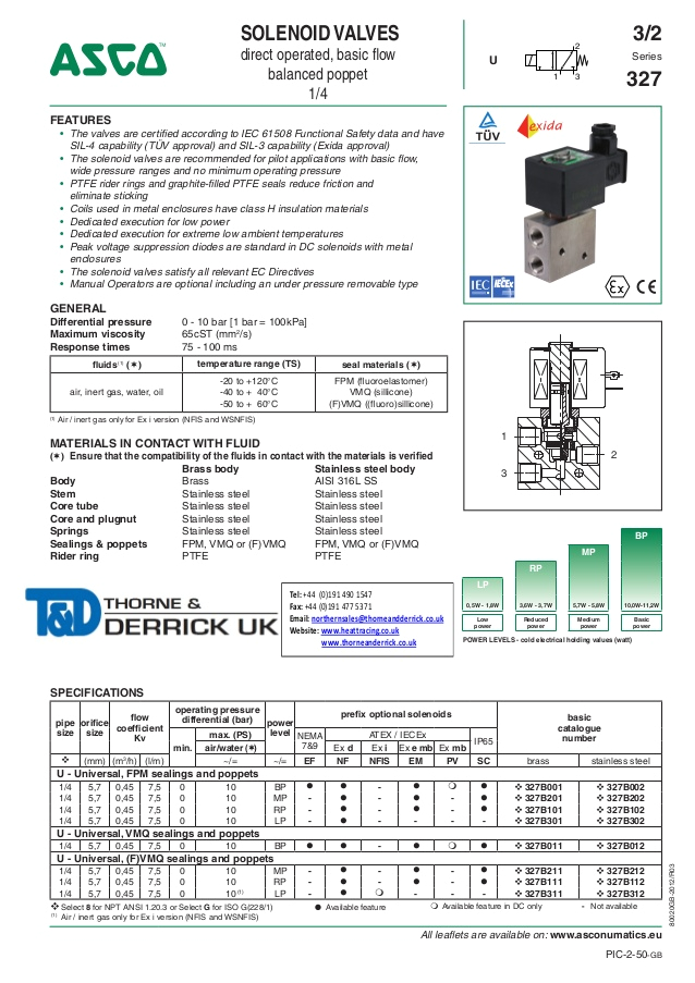
asco solenoid valves optional features
A set of wiring diagrams may be required by the electrical inspection authority to agree to membership of the dwelling to the public electrical supply system.
Wiring diagrams will afterward affix panel schedules for circuit breaker panelboards, and riser diagrams for special services such as flare alarm or closed circuit television or other special services.
You Might Also Like :
asco solenoid valve wiring diagram another picture:

asco valve 8260 series plastic body two manualzz com
connectors 881 asco numatics
asco nfg327b021 g1 4 3 2 universal solenoid valve no
asco solenoid valve wiring diagram free wiring diagram variety of asco solenoid valve wiring diagram a wiring diagram is a streamlined standard pictorial representation of an electric circuit it shows the parts of the circuit as simplified shapes and also the power as well as signal links in between the tools 4 engineering information solenoid valves asco asco valves have a solenoid mounted directly on the valve body the core is enclosed in a sealed tube providing a compact leaktight assembly direct acting valves figures 1a 1b when the solenoid is energized in a direct acting valve the core directly opens the orifice of a normally closed valve or closes the orifice of a no rm aly op env wh d giz spring returns the valve to its asco solenoid valve wiring diagram collection wiring asco solenoid valve wiring diagram collection asco atex solenoid valves 327 series spec sheet solenoid valve wiring diagram tww plc wiring rh thewolfweb solenoid valve wiring diagram tww plc wiring rh thewolfweb asco em wsem atex iec ex flameproof explosion proof operator hazardou solenoid valves asco redhat general service miniature asco solenoid valves control critical flow of air gas water oil and steam in applications spanning numerous industries our portfolio ranges from two position on off valves to flow control systems that impact thousands of users solenoid valve wiring schematic free wiring diagram assortment of solenoid valve wiring schematic a wiring diagram is a streamlined traditional pictorial representation of an electric circuit it reveals the elements of the circuit as simplified forms as well as the power as well as signal connections between the devices installation maintenance instructions series 8016g h solenoid valves used for steam service or when a class h solenoid is used seetemperature limitations section for solenoid identification and nameplate retainer for service when installed just as a solenoid and not attached to an asco valve the core has a 0 250 28 unf 2b tapped hole 0 38 minimum full thread solenoid valves 3 2 asco flfififl ˆˇ 80020 gb 2018 r01 all leaflets are available on www asco com 3 explanation of temperature ranges of solenoid valves valve temperature range the valve temperature range ts is determined by the selected seal material the temperature series 881 din electrical connectors asco allowing access to the wiring for easy checking of power supply without unplugging the connector and without interrupting operation of the solenoid valve din electrical connectors specifications description cable length cable o d wire cross section max voltage type catalog number 11mm 18mm 11mm 18mm m inches mm inches mm2 v nbr nbr vmq pilot valves in the process industry asco pilot valves in the process industry actuator interface types and pilot valve function pilot valve location and interface for pilot valves in this catalogue the following definition is used solenoid pilot valves are valves used to control the flow of air to pneumatic actuators which in turn are moving process valves to their required open or closed position basically three alternatives installing an asco solenoid valve avoid typical problems when installing a solenoid valve presented by industrial equipment co sales indeco tx com 713 928 3181


