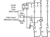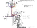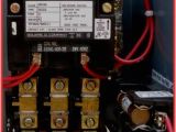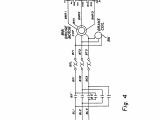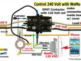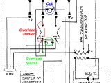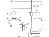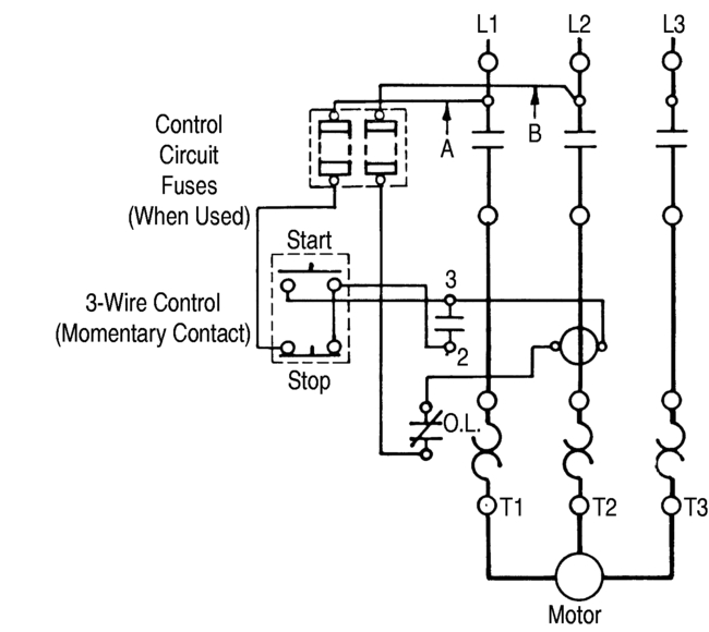
Allen Bradley Motor Control Wiring Diagrams– wiring diagram is a simplified gratifying pictorial representation of an electrical circuit. It shows the components of the circuit as simplified shapes, and the capacity and signal connections between the devices.
A wiring diagram usually gives instruction virtually the relative approach and conformity of devices and terminals on the devices, to incite in building or servicing the device. This is unlike a schematic diagram, where the accord of the components’ interconnections upon the diagram usually does not have the same opinion to the components’ bodily locations in the over and done with device. A pictorial diagram would law more detail of the being appearance, whereas a wiring diagram uses a more symbolic notation to heighten interconnections greater than innate appearance.
A wiring diagram is often used to troubleshoot problems and to create definite that all the links have been made and that all is present.
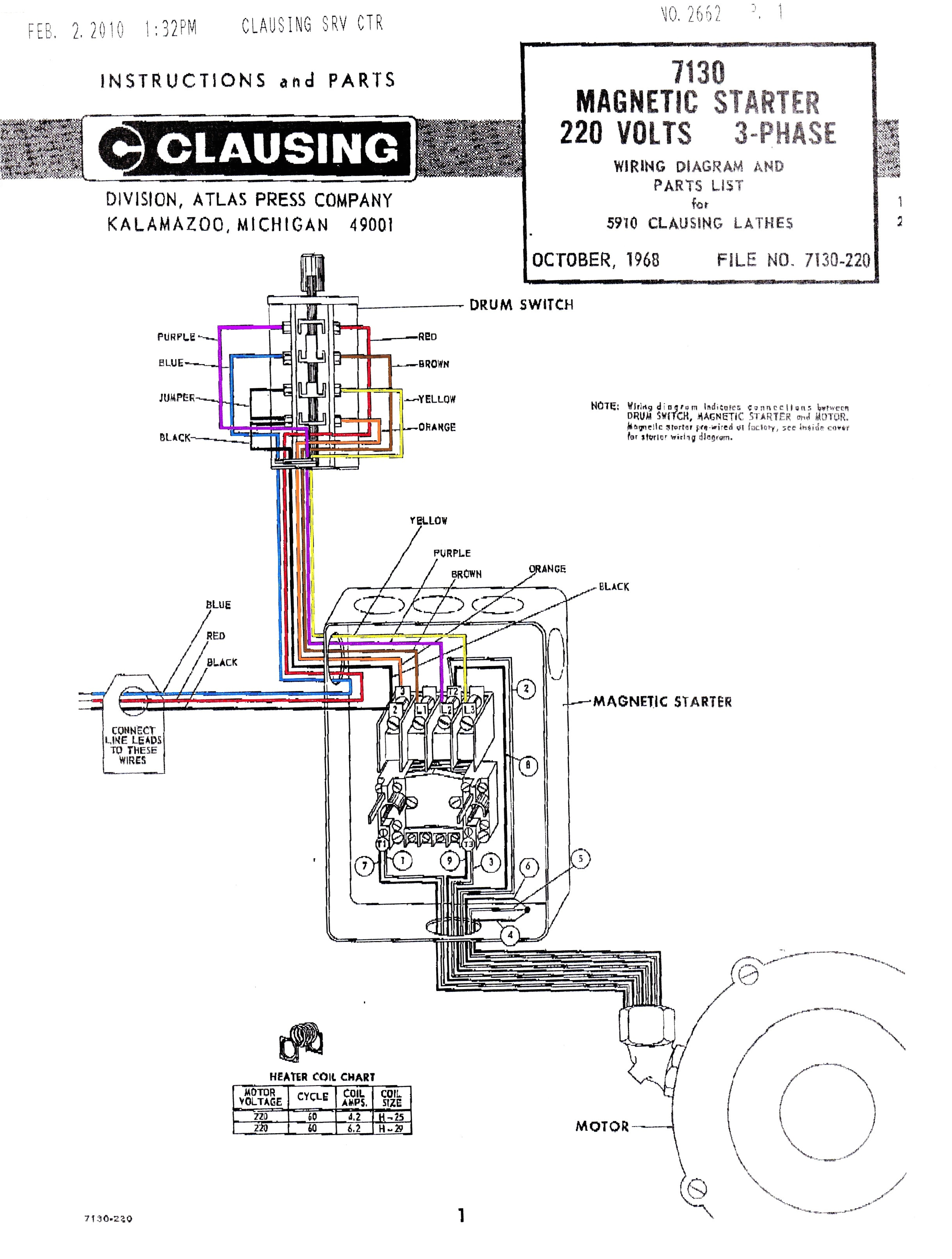
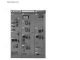
cutler hammer wiring diagrams wiring diagram centre
Architectural wiring diagrams discharge duty the approximate locations and interconnections of receptacles, lighting, and permanent electrical services in a building. Interconnecting wire routes may be shown approximately, where particular receptacles or fixtures must be upon a common circuit.
Wiring diagrams use adequate symbols for wiring devices, usually interchange from those used on schematic diagrams. The electrical symbols not solitary feint where something is to be installed, but as well as what type of device is creature installed. For example, a surface ceiling well-ventilated is shown by one symbol, a recessed ceiling lively has a vary symbol, and a surface fluorescent fresh has unconventional symbol. Each type of switch has a every other tale and for that reason get the various outlets. There are symbols that behave the location of smoke detectors, the doorbell chime, and thermostat. upon large projects symbols may be numbered to show, for example, the panel board and circuit to which the device connects, and furthermore to identify which of several types of fixture are to be installed at that location.
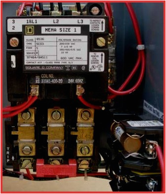
ab motor starter wiring diagram woodworking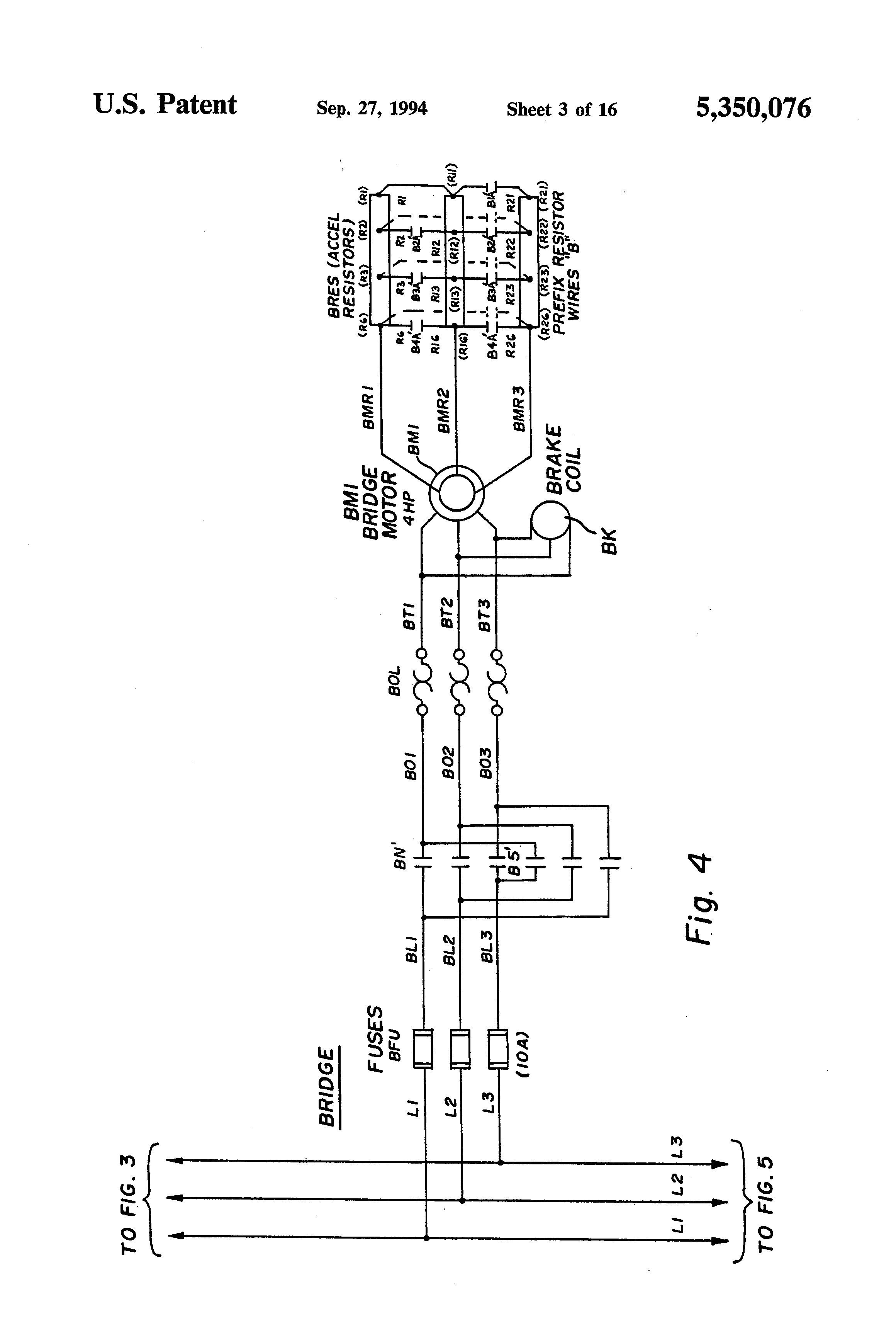
allen dley vfd wiring diagram wiring diagram centre
A set of wiring diagrams may be required by the electrical inspection authority to espouse attachment of the quarters to the public electrical supply system.
Wiring diagrams will with include panel schedules for circuit breaker panelboards, and riser diagrams for special facilities such as flame alarm or closed circuit television or supplementary special services.
You Might Also Like :
allen bradley motor control wiring diagrams another graphic:
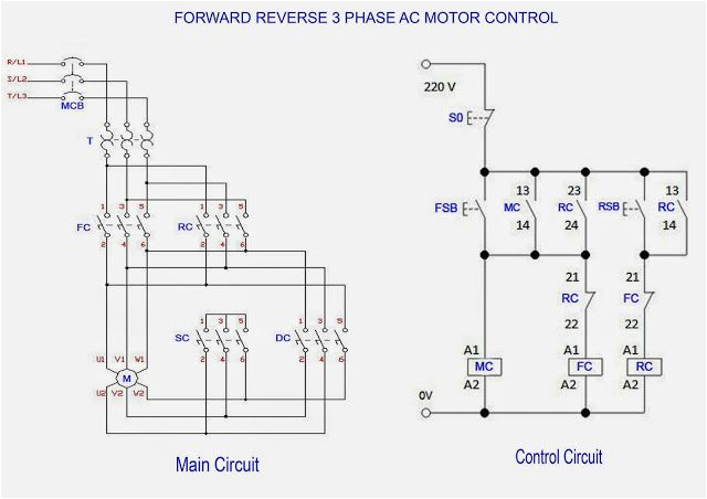
and reverse motor diagram motor repalcement parts and diagram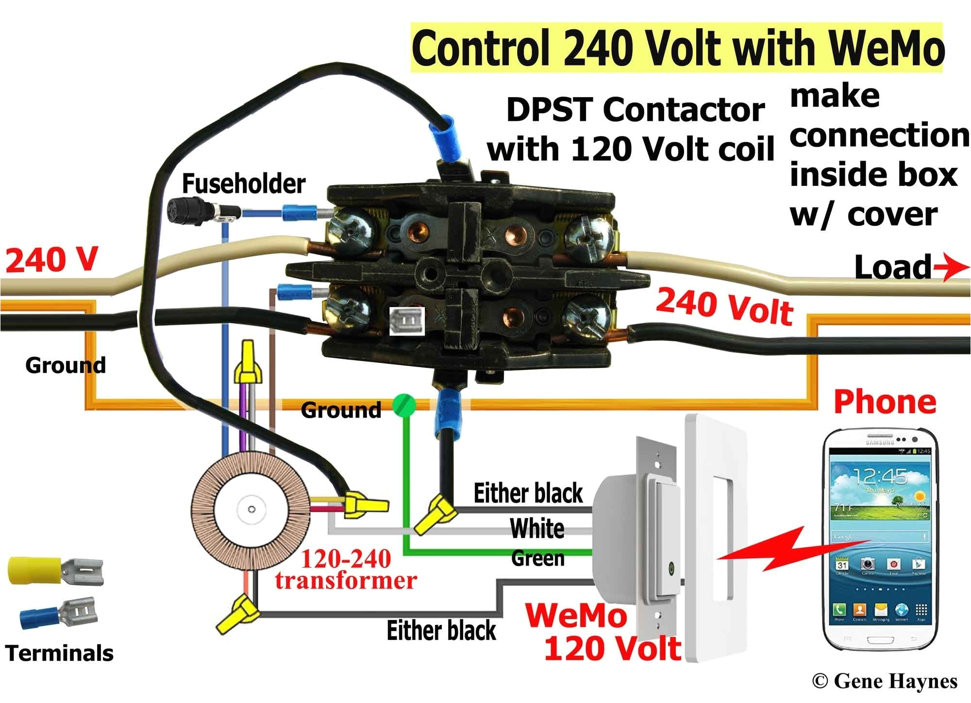
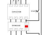
circuit diagram wiring a contactor wiring diagram used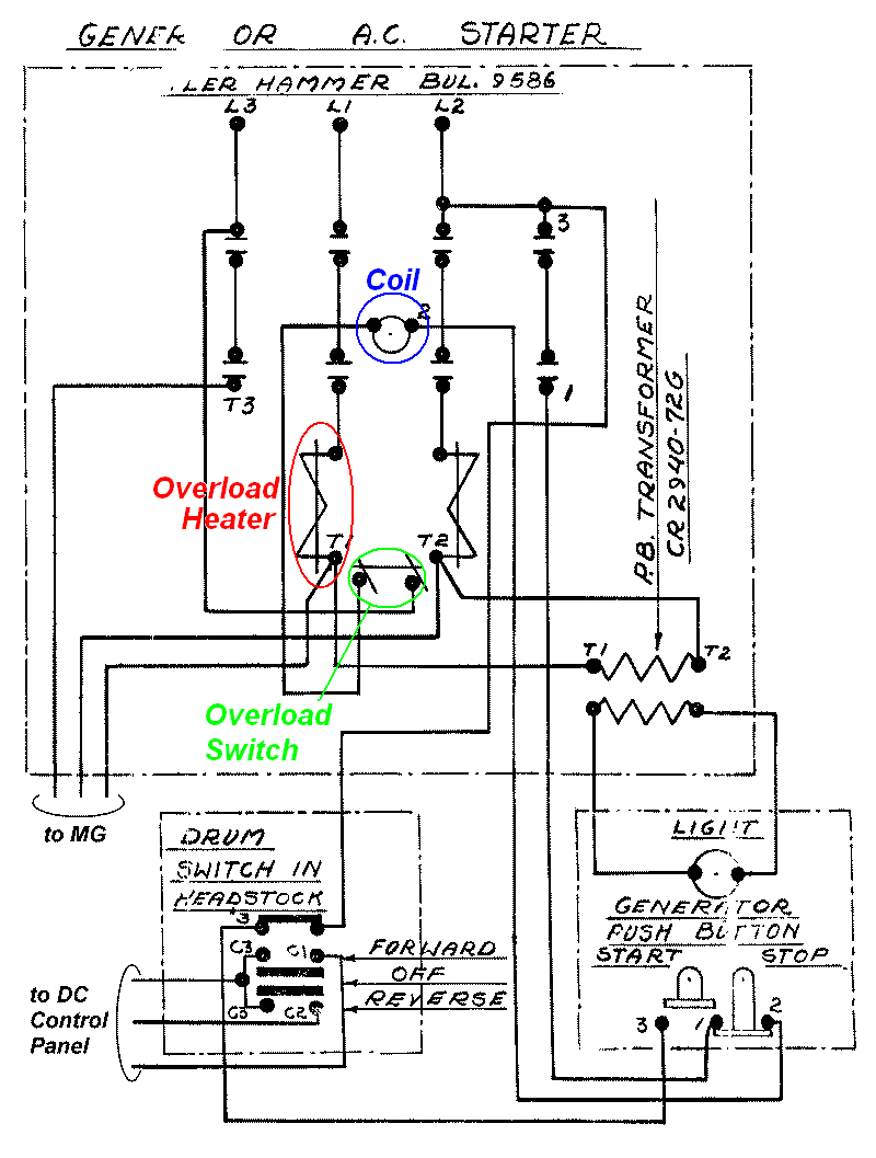
cutler hammer wiring diagrams wiring diagram centre
gi 2 0 typical wiring diagrams wiring diagrams ww introduction this booklet has been prepared as a guide to some of the useful ways allen bradley s manual and magnetic across the line starters allen bradley soft starter wiring diagram gallery wiring allen bradley soft starter wiring diagram architectural electrical wiring layouts show the approximate places as well as affiliations of receptacles lights as well as irreversible electric solutions in a structure wiring diagram contactor how to wire a for 3 phase wiring diagram contactor how to wire a for 3 phase throughout allen bradley motor control diagrams with in contactor wiring diagram wiring diagram contactor how to wire a for 3 phase throughout allen bradley motor control diagrams with in contactor wiring diagram allen bradley motor control wiring diagrams diagram post tagged allen bradley motor control center wiring diagrams allen bradley motor control wiring diagrams allen bradley motor control wiring diagrams wiring post tagged allen bradley motor control center wiring diagrams allen bradley motor control wiring diagrams download by size handphone tablet desktop original size vfd motor control circuit diagram wiring diagram gallery vfd motor control circuit diagram 3 phase motor starter control circuit wiring diagram components with 2100 wd1 wiring diagrams plccenter cn wiring diagram reference resource for centerline motor control centers 3 class ii interconnected units class ii motor control centers are the same as class i but with centerline 2100 motor control centers program guide allen bradley distributor or rockwell automation sales representative for derating requirements 12 rockwell automation publication 2100 ca004d en p october 2018 chapter 1 centerline 2100 motor control centers allen bradley centerline 2100 technical data manual view and download allen bradley centerline 2100 technical data manual online motor control center with intellicenter technology using an ethernet ip network centerline 2100 controller pdf manual download motor control ab rockwellautomation com control load switches bulletin 194 control and load switches offer you state of the art solutions for almost any application you can use bulletin 194e load switches and bulletin 194l control load switches as at motor disconnecting means per article 430 j of the national electrical code
